
Reed relay

A technology of magnetic reed relay and magnetic reed switch, applied in the direction of electromagnetic relay, relay, detailed information of electromagnetic relay, etc., can solve the problems of increased volume, increased impedance, and inability to meet the size limit of miniaturization

Inactive Publication Date: 2010-12-29
BAIRONG ELECTRONICS
View PDF1 Cites 4 Cited by
  • Summary
  • Abstract
  • Description
  • Claims
  • Application Information

AI Technical Summary

Problems solved by technology

[0002] China Taiwan Patent Application No. 94137648 discloses a reed relay. The reed relay adopts a single coil winding structure, and the finished product must meet the customer's needs. In terms of current and impedance, it is generally difficult to achieve the winding structure of a single coil, because when a thicker coil is used to meet the low driving current, it will increase the volume and cannot meet the size limit of miniaturization. Impedance increases when the coil is wound, so it is necessary to improve
[0003] In addition, in terms of control, the control of a single coil is relatively simple, and the matched circuit only needs a single signal source to achieve it. However, when there are switch control requirements for multiple signal sources, only one switch change can not meet the use requirements.

Method used


Image

  • Reed relay
  • Reed relay
  • Reed relay

Examples


Embodiment Construction

[0011] Below in conjunction with accompanying drawing and embodiment the present invention is described in detail:

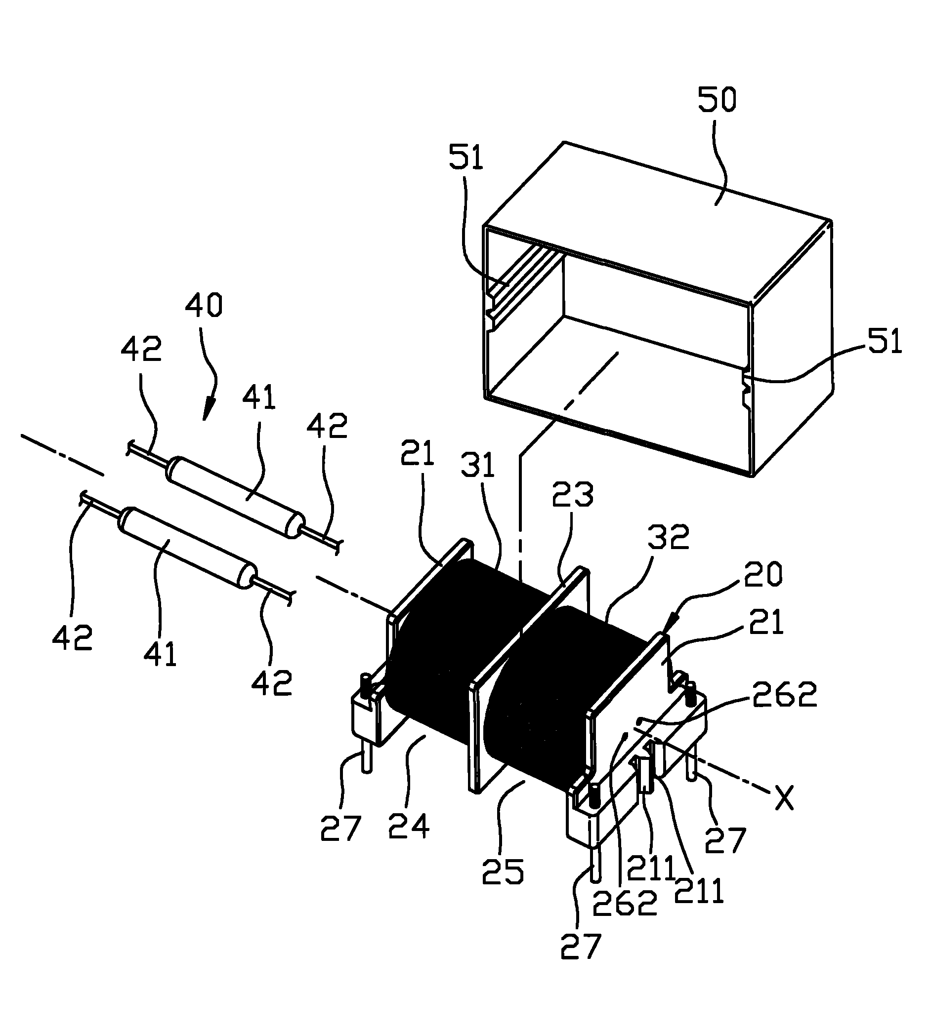
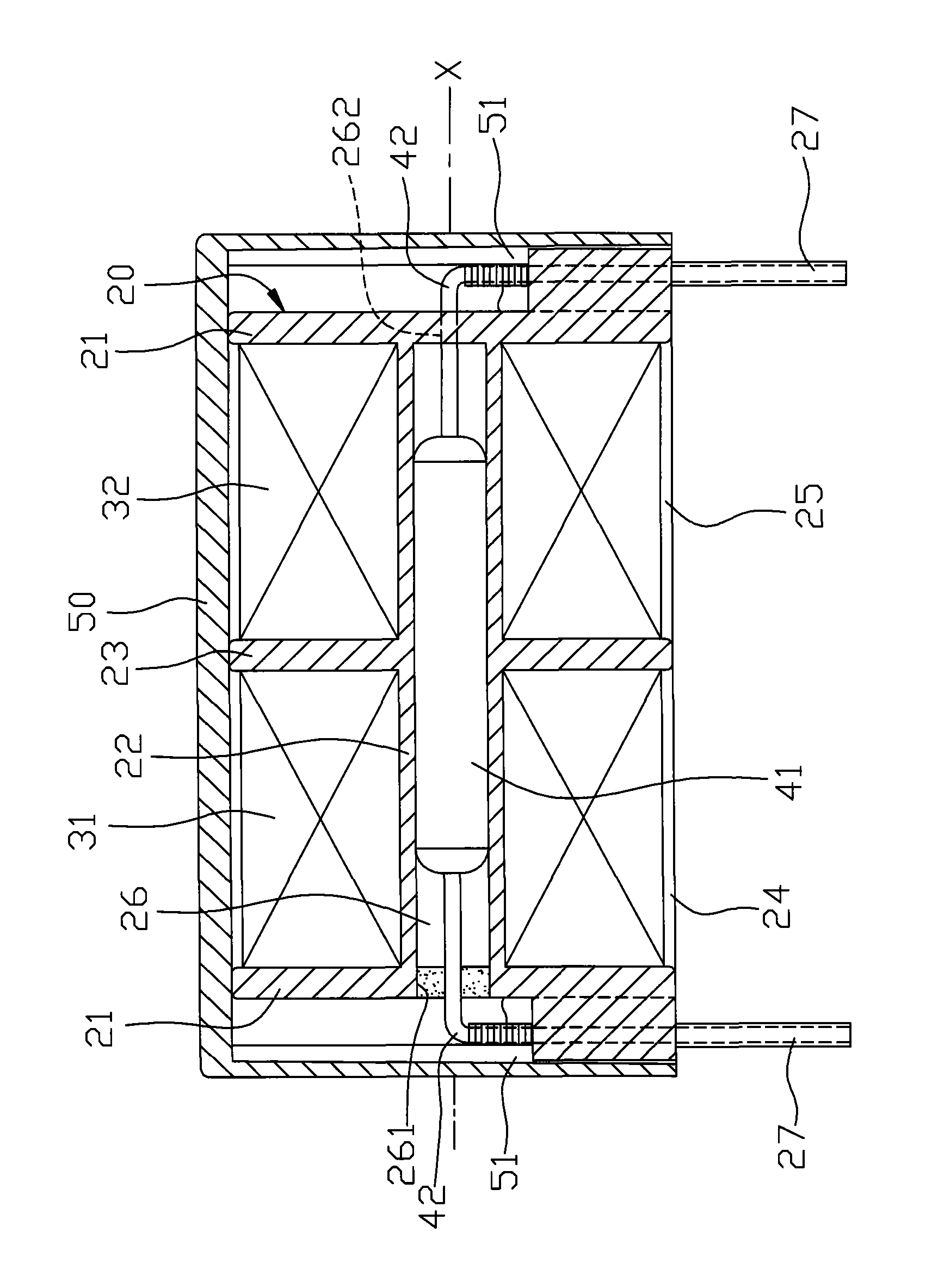
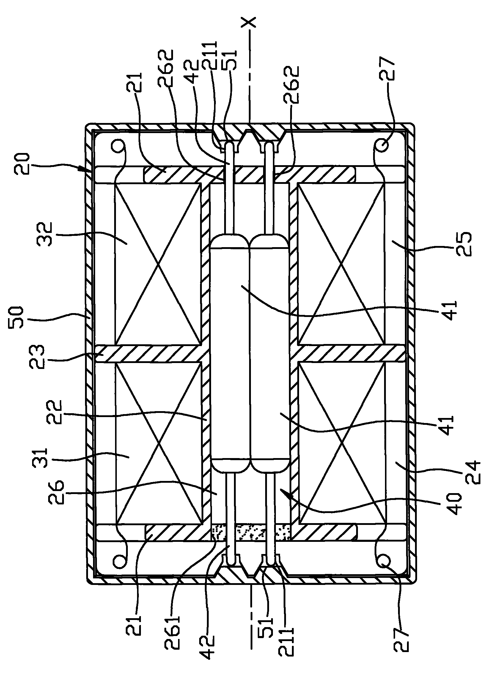
[0012] Such as figure 1 , 2 , 3, the preferred embodiment of the reed relay 200 of the present invention includes a winding frame 20, a first coil 31, a second coil 32, a reed switch unit 40 and a housing 50.

[0013] The bobbin frame 20 includes two spaced apart side walls 21, a tube wall 22 connected between the side walls 21 around an axis X, and a tube wall 22 protruding from the tube wall 22 and interposed between the side walls 21. Between the partition wall 23, a first winding slot 24 between the partition wall 23 and one of the side walls 21, a second winding slot 25 between the partition wall 23 and the other side wall 21, A chamber 26 connecting the side wall 21 and the tube wall 22 along the axis X, and a plurality of electrodes 27 respectively disposed on the side wall 21 .

[0014] Each sidewall 21 has a plurality of guide grooves 211 that are lo...


PUM


Abstract

The invention relates to a reed relay which comprises a bobbin, a first coil, a second coil and a reed switching unit, wherein the bobbin comprises two side walls arranged at an interval, a barrel wall which is around an axis and connected between the side walls, a partition wall which is protruded out of the barrel wall and arranged between the side walls, a first winding groove which is positioned between the partition wall and one side wall, a second winding groove which is positioned between the partition wall and the other side wall, an accommodating chamber which is communicated with the side walls and the barrel wall along the axis and a plurality of electrodes which are respectively arranged on the side walls; the first coil and the second coil are respectively wound on the first winding groove and the second winding groove and electrically connected with the electrodes respectively; and the reed switching unit is arranged in the accommodating chamber and is provided with a plurality of pins extending out of the bobbin.

Description

technical field [0001] The invention relates to a relay, in particular to a magnetic reed relay. Background technique [0002] China Taiwan Patent Application No. 94137648 discloses a reed relay. The reed relay adopts a single coil winding structure, and the finished product must meet the customer's needs. In terms of current and impedance, it is generally difficult to achieve the winding structure of a single coil, because when a thicker coil is used to meet the low driving current, it will increase the volume and cannot meet the size limit of miniaturization. Impedance increases when the coil is wound, so improvement is necessary. [0003] In addition, in terms of control, the control of a single coil is relatively simple, and the matched circuit only needs a single signal source to achieve it. However, when there are switch control requirements for multiple signal sources, only one switch change can not meet the use requirements. Contents of the invention [0004] The...

Claims


Application Information

Patent Timeline
IPC IPC(8): H01H51/27H01H50/40
Inventor 吴温兰
Owner BAIRONG ELECTRONICS
Learn More