Pressure sensor with diaphragm and depth gauge incorporating such sensor

A pressure sensor and diaphragm technology, applied in the field of depth gauges, can solve problems such as limiting the elastic deformation of the diaphragm and achieve high sensitivity

Active Publication Date: 2010-12-29
THE SWATCH GRP RES & DEVELONMENT LTD
View PDF5 Cites 9 Cited by
  • Summary
  • Abstract
  • Description
  • Claims
  • Application Information

AI Technical Summary

Problems solved by technology

In this case, the diaphragm is bulky, the raised edge is only used for sealing, and most importantly, the bend in the U is an area of ​​stress concentration caused by fluid pressure, limiting what the diaphragm can do before entering the plastic domain. undergone elastic deformation

Method used


Image

  • Pressure sensor with diaphragm and depth gauge incorporating such sensor
  • Pressure sensor with diaphragm and depth gauge incorporating such sensor
  • Pressure sensor with diaphragm and depth gauge incorporating such sensor

Examples


Embodiment Construction

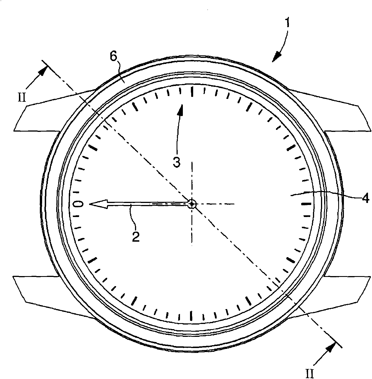
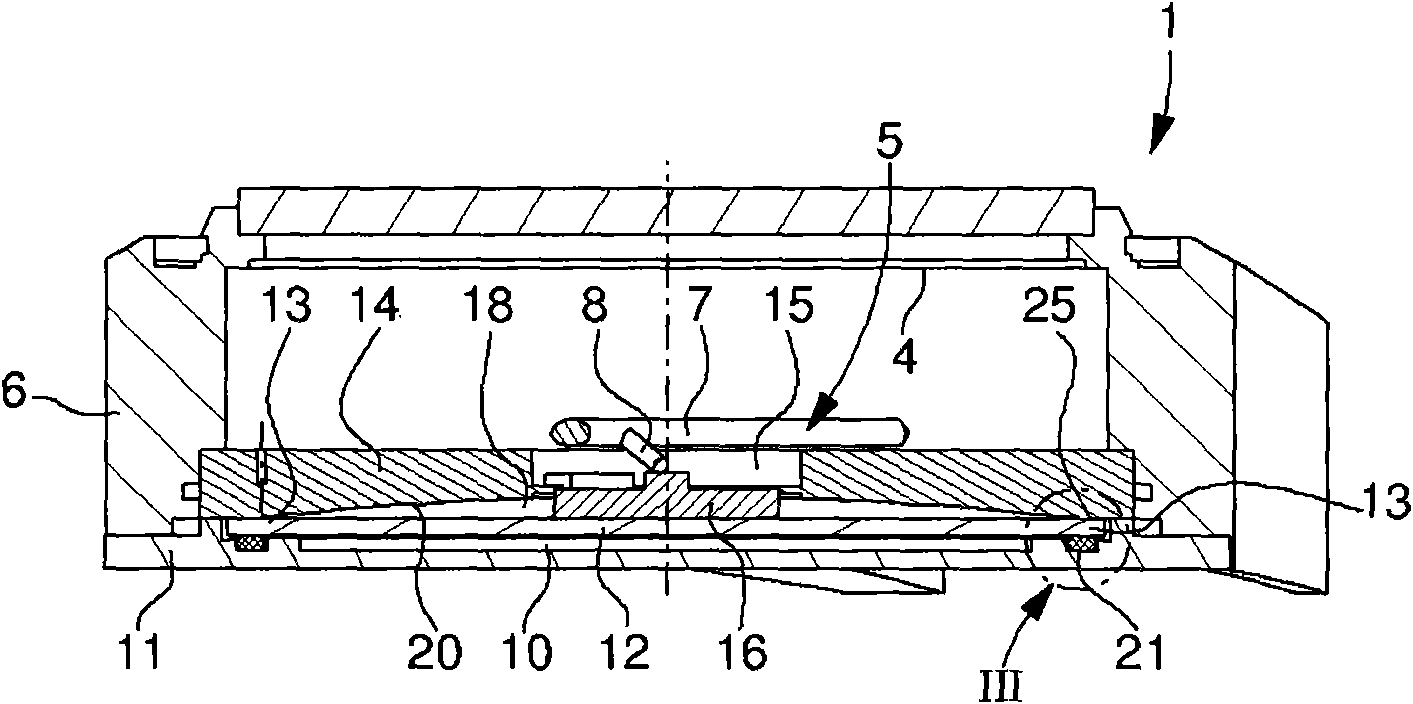
[0015] Figure 1-3 A depth gauge 1 is schematically shown worn on a diver's wrist using a strap not shown, for indicating the depth of the water via a pointer 2 using a pressure sensor housed in a depth gauge housing 6 5 to rotate relative to scale 3 of dial 4. The pressure sensor is connected to the pointer 2 by means of a mechanical transmission, in particular a rotating shaft 7 with a transverse probe 8 . It should be noted that the depth gauge 1 can be combined with a watch inside the same case, but this is not essential.

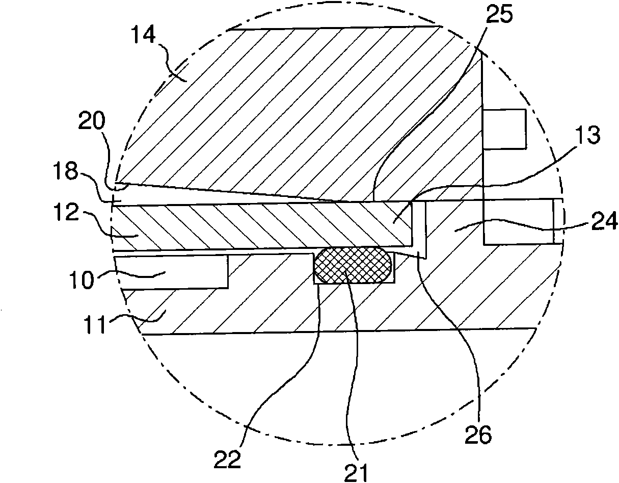
[0016] The pressure sensor 5 is mounted on a rear cover 11 of the housing, which generally forms the main body of the sensor. The sensor is arranged above a pressure chamber 10 formed in the rear cover 11 and communicates with the exterior of the housing via a hole (not shown) so that the fluid contained in the chamber is subjected to a pressure mainly around the depth gauge. The pressure sensor 5 has a flat annular diaphragm 12 whose peripheral regi...


PUM


Abstract

The invention concerns a pressure sensor (5), particularly for a depth gauge (1), capable of having a high level of precision, owing to sufficient elastic deflection amplitude of the diaphragm (or membrane), while avoiding any risk of plastic deformation. The diaphragm (12) is formed by a flat metal disc. The peripheral region (13) thereof is neither welded nor inset, but it is pre-stressed against a stop strip (25) with a closed, preferably circular contour, and can pivot on the stop strip (25) when the diaphragm bends under the effect of fluid pressure in the pressure chamber (10). The pre-stressing may be achieved via a sealing gasket (21) located opposite the stop strip (25). Between said strip and a central aperture (15), a concave stop surface (20) limits the deflection of the diaphragm (12) and prevents any plastic deformation in the event of excessive pressure. Manufacture of the diaphragm is simple, with a high level of reproducibility, assembly is easy and the seal quality is high.

Description

technical field [0001] The invention relates to a pressure sensor comprising: a body having a cavity for receiving a pressurized fluid and a support element surrounding the cavity; a cover fastened to the body with a stop strip, the stop The belt has a closed contour corresponding to the supporting element of the body; a diaphragm is arranged between the body and the cover so as to seal the pressure chamber and is able to bend under the influence of the pressure difference between its two sides, wherein the peripheral area of ​​the diaphragm disposed between the support element and the stop band; and a transmission mechanism connected to the central region of the diaphragm for transmitting diaphragm deflection data to a measuring or indicating mechanism. The invention also relates to a depth gauge comprising such a pressure sensor. Background technique [0002] In the pressure transducers used, especially in manometers or depth gauges, the diaphragm (also called "membrane")...

Claims


Application Information

Patent Timeline
Patent Type & Authority Applications(China)
IPC IPC(8): G01L7/08G01B13/14
CPCG01L7/08G01C5/06B63C11/02G04G21/02G01L7/082
Inventor N·雷博德
Owner THE SWATCH GRP RES & DEVELONMENT LTD
Why Eureka
Try Eureka