Shell and electronic device using the same

A shell and substrate technology, applied in lighting devices, electrical equipment shells/cabinets/drawers, electric light sources, etc., can solve the problems of poor practicability, disadvantage, and affect the use effect, etc., and achieves difficult to shift, stable use effect, and occupation small space effect

Inactive Publication Date: 2010-12-22
SHENZHEN FUTAIHONG PRECISION IND CO LTD
View PDF0 Cites 3 Cited by
  • Summary
  • Abstract
  • Description
  • Claims
  • Application Information

AI Technical Summary

Problems solved by technology

Since the fluorescent ink needs to absorb the light source in the bright place before it can emit light in the dark place, the luminous conditions are limited, and the luminous life of the fluorescent ink is short
Due to the large size of the LED lamp, the installation of the LED lamp inside the housing will inevitably increase the thickness of the housing. In addition, the power consumption of the LED lamp is relatively large, and it is easy to consume the energy of the battery of the electronic device, so the practicability is poor.
[0003] For this reason, people attach or detachably install the sheet-shaped electroluminescent element on the casing of the product. This method of attaching or installing is easy to cause displacement and damage of the electroluminescent element during use. It is worn out, thereby affecting its use effect, and it is necessary to reserve a necessary installation space on the housing to accommodate the electroluminescent element, which is not conducive to reducing the thickness of the housing and simplifying the structure of the housing

Method used


Image

  • Shell and electronic device using the same
  • Shell and electronic device using the same
  • Shell and electronic device using the same

Examples


Embodiment Construction

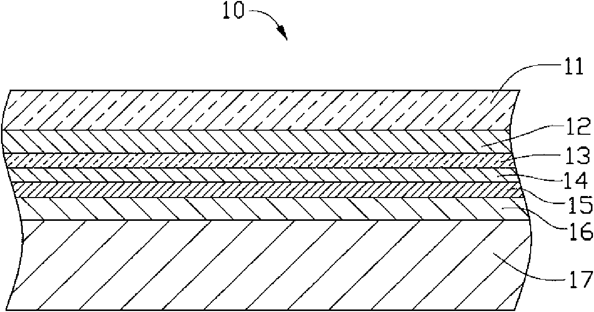
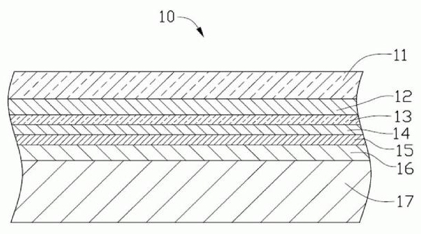
[0011] see figure 1 As shown, the casing 10 of a preferred embodiment of the present invention includes an outer layer 11 and a base 17, and the casing 10 also includes a decorative layer 12 fixed between the outer layer 11 and the base 17, a first conductive layer 13. A light emitting layer 14 , an insulating layer 15 and a second conductive layer 16 .

[0012] The outer layer 11 is a transparent plastic layer, which can be selected from polypropylene (PP), polyamide (PA), polycarbonate (PC), polyethylene terephthalate (PET) and polymethacrylate Any of the esters (PMMA). The outer skin 11 may be hardened to make its surface smooth and scratch-resistant. The thickness of the outer layer 11 is about 0.1-0.20mm.

[0013] The decoration layer 12 is a colored ink layer, and the ink can be transparent or translucent. The decoration layer 12 can be a product's trademark or a decorative pattern, which is formed on a part or all of a surface of the outer layer 11 by screen printin...


PUM


Abstract

The invention provides a shell, which comprises an outer surface layer and a base. The shell further comprises a first conductive layer, an illuminating layer and a second conductive layer which are arranged between the outer surface layer and the base, wherein the illuminating layer is arranged between the first conductive layer and the second conductive layer; the first conductive layer and the second conductive layer are respectively provided with an electric connecting port; and the base is injected and molded on the second conductive layer. The invention also provides an electronic device using the shell.

Description

technical field [0001] The invention relates to a casing, in particular to a luminous casing and an electronic device using the casing. Background technique [0002] Currently, the casing of the electronic device is usually equipped with a light emitting function to attract consumers' attention. Existing methods for making a luminous housing include: printing fluorescent ink on the housing or arranging LED lights inside the housing. Because the fluorescent ink needs to absorb the light source in the bright place before it can emit light in the dark place, the lighting conditions are limited, and the fluorescent ink has a short luminous life. Due to the large size of the LED lamp, the installation of the LED lamp inside the casing will inevitably increase the thickness of the casing. In addition, the power consumption of the LED lamp is relatively large, and it is easy to consume the energy of the battery of the electronic device, so the practicability is poor. [0003] For...

Claims


Application Information

Patent Timeline
Patent Type & Authority Applications(China)
IPC IPC(8): H05B33/12H05K5/00
CPCH04M1/0283H04M1/22
Inventor 曹丙丁熊文林翁东生徐红喜晏启全朱典明
Owner SHENZHEN FUTAIHONG PRECISION IND CO LTD
Why Eureka
Try Eureka