


Quick Research
Generate reliable direction feasibility study reports for your R&D in just a few steps.

Technical Q&A
Discover and master advanced knowledge NOW. Basics, ideas, possibilities, all at once.

Find Solutions
As an expert in R&D theories, this can generate solutions to your technical problems instantly.

Evaluate Feasibility
Analyze your overall solution with one click, know your potential R&D risks in advance.

Monitor Landscape
Get weekly tech updates, stay abreast of the latest tech innovations and key insights.
Speaker
A loudspeaker and damper technology, applied in the field of thin and small loudspeakers, can solve the problems of loss of thinness of the loudspeaker, inability to increase the distance between the frame and the vibration plate, etc. Effect
- Summary
- Abstract
- Description
- Claims
- Application Information
AI Technical Summary
Problems solved by technology
Method used
Image

Examples
no. 1 example
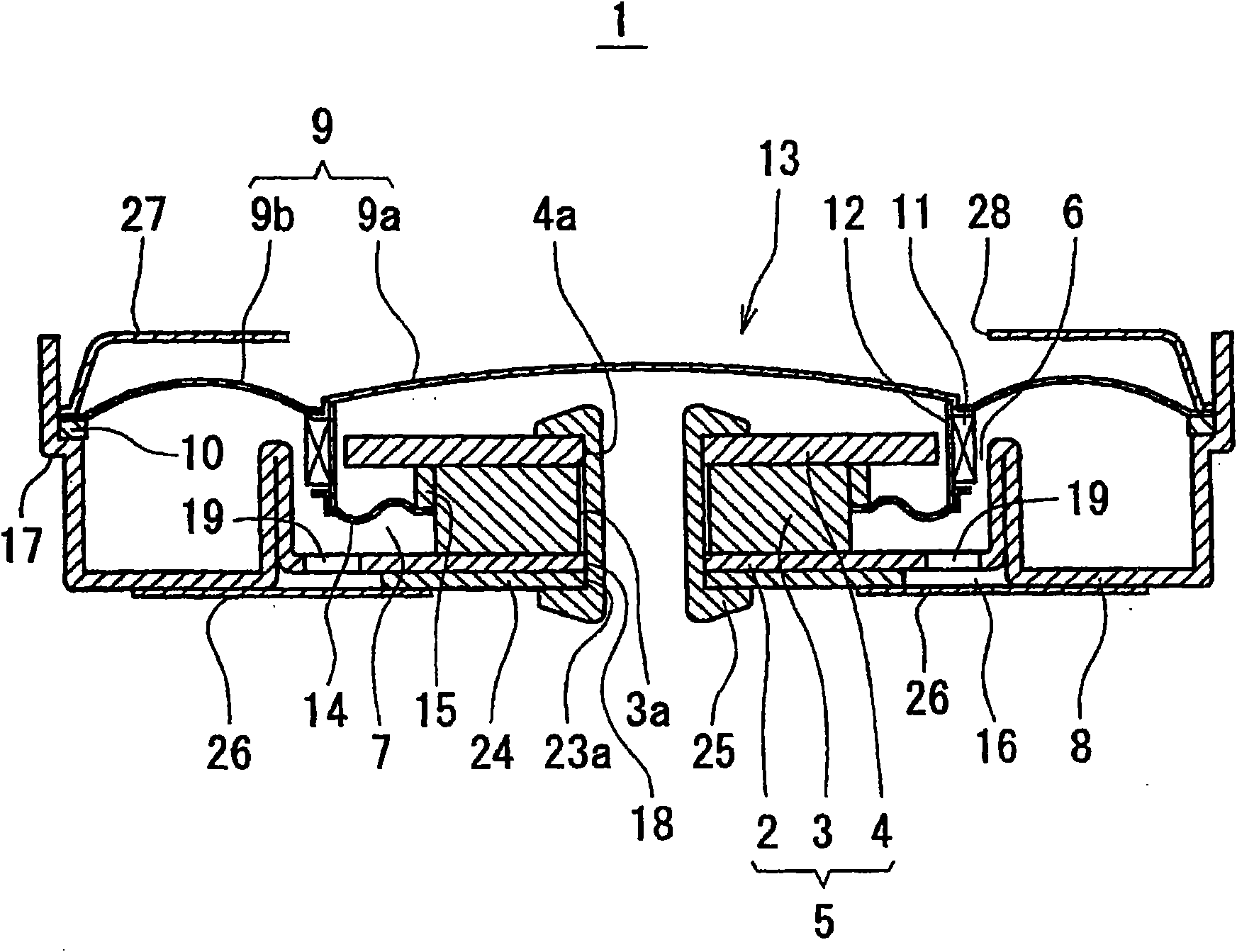
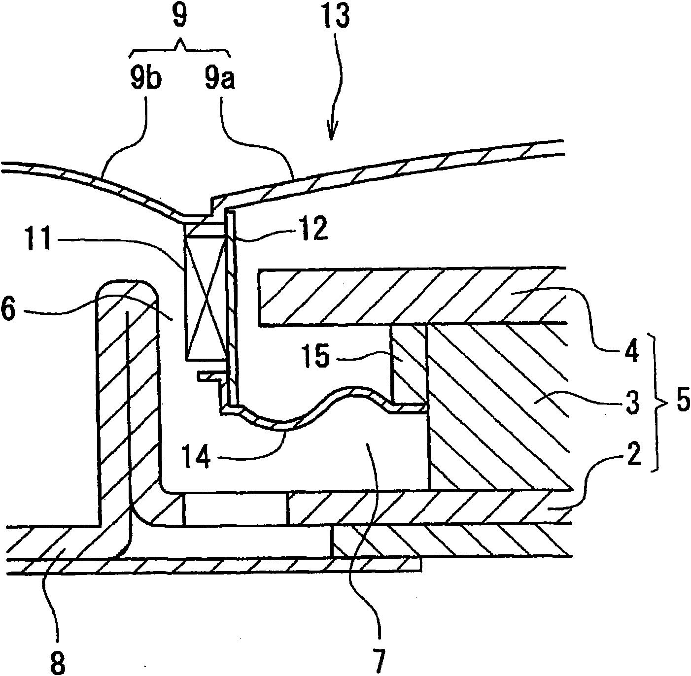
[0030] figure 1 is a sectional view of the speaker according to the first embodiment of the present invention. The loudspeaker 1 consists of a bottomed cylindrical yoke 2, a cylindrical magnet 3 and a disc-shaped pole piece 4 to form a circular inner magnetic magnetic circuit 5, wherein the yoke 2 is formed of magnetic materials , the magnet 3 is formed by a permanent magnet, and is loaded and fixed in the yoke 2, and the pole piece 4 is formed by a magnetic material, and is fixed on the upper surface of the magnet 3, between the pole piece 4 and the yoke 2 The magnet 3 is sandwiched between the bottom plate parts. The diameter of the pole shoe 4 is smaller than the inner diameter of the yoke 2, and the gap between the outer peripheral surface of the pole shoe 4 facing the radial direction of the magnetic circuit 5 and the inner peripheral surface of the circumferential side wall of the yoke 2 forms a magnetic gap 6 of the magnetic circuit 5 . The diameter of the magnet 3 i...
no. 2 example
[0054] Figure 4 It is an enlarged cross-sectional view of a main part of a speaker according to a second embodiment of the present invention. This loudspeaker 30 is provided with a damper 14a integrally formed with the voice coil bobbin 12 instead of the damper 14 of the loudspeaker 1 in the first embodiment, which is different from the loudspeaker 1 of the first embodiment, and the other structures are the same as those of the first embodiment. The speaker 1 of one embodiment is the same, and therefore the same reference numerals are attached to the same structure, and detailed description thereof will be omitted. As shown in the speaker 30 of this embodiment, since the damper 14a is integrated with the voice coil bobbin 12, the number of parts and the number of assembly steps of the vibration system 13 can be reduced, thereby improving productivity.
no. 3 example
[0056] Figure 5It is an enlarged cross-sectional view of a main part of a speaker according to a third embodiment of the present invention. This speaker 40 is provided with a voice coil bobbin 12a integrated with the dome portion 9a of the diaphragm 9 instead of the voice coil bobbin 12 of the speaker 1 of the first embodiment, and the damper 14 is formed with the voice coil bobbin 12a integrated with the dome portion 9a of the diaphragm 9. The bobbin 12a is different from the speaker 1 of the first embodiment in that it is different from the speaker 1 of the first embodiment, and the other structures are the same as the speaker 1 of the first embodiment, so the same reference numerals are assigned to the same structures, and details are omitted. illustrate. As shown in the speaker 40 of this embodiment, since the damper 14 and the voice coil bobbin 12a are formed separately, and the voice coil bobbin 12a is integrated with the dome portion 9a of the diaphragm 9, the number ...
PUM
 Abstract
Description
Claims
Application Information
 - R&D Engineer
- R&D Manager
- IP Professional
- Industry Leading Data Capabilities
- Powerful AI technology
- Patent DNA Extraction
Browse by: Latest US Patents, China's latest patents, Technical Efficacy Thesaurus, Application Domain, Technology Topic, Popular Technical Reports.
© 2024 PatSnap. All rights reserved.Legal|Privacy policy|Modern Slavery Act Transparency Statement|Sitemap|About US| Contact US: help@patsnap.com