
Transformer structure

A technology for transformers and winding bases, applied in transformers, fixed transformers, transformer/inductor cores, etc., can solve problems such as flashover, large voltage difference, and damage to transformer 2

Inactive Publication Date: 2012-10-03
DELTA ELECTRONICS INC
View PDF5 Cites 2 Cited by
  • Summary
  • Abstract
  • Description
  • Claims
  • Application Information

AI Technical Summary

Problems solved by technology

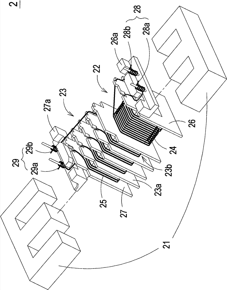
[0007] Since the transformer 2 is used in the power supply system for driving the discharge lamp, its driving voltage is usually high voltage, so the primary winding 24 and the secondary winding 25 may cause flashover due to large voltage difference and insufficient electrical safety distance.
In addition, the transformer 2 often has a gap between the winding wire and the magnetic core group 21 because the magnetic core group 21 is partially exposed and adjacent to the primary winding 24 of the first winding part 22 and the secondary winding 25 of the second winding part 23. Insufficient electrical safety distance
In addition, in the transformer 2, because the primary winding 24 and the secondary winding 25 directly make a part of the coils exposed under the first winding part 22 and the second winding part 23 respectively when they are looped back, it is easy to be affected by the safety distance. Insufficient flashover (short circuit) occurs, resulting in damage to the transformer 2

Method used


Image

  • Transformer structure
  • Transformer structure
  • Transformer structure

Examples


Embodiment Construction

[0059] Some typical embodiments embodying the features and advantages of the present invention will be described in detail in the following description. It should be understood that the invention is capable of various changes in different forms without departing from the scope of the invention, and that the description and drawings therein are illustrative in nature and are not intended to limit the invention.

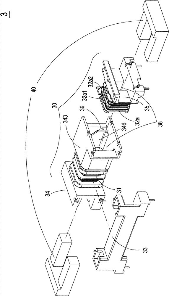
[0060] Please refer to Figure 3A and Figure 3B , which is a schematic structural diagram of a transformer in a preferred embodiment of the present invention. As shown in the figure, the transformer 3 of the present invention mainly includes a bobbin set 30 , a magnetic core sleeve 33 and a magnetic core set 40 . Wherein, the bobbin set 30 includes a first through channel 38 , a primary winding base 34 and a first secondary winding base 35 . The primary winding base 34 is wound with at least one primary winding 31 and has a first sheath 343 . The first secondary w...


PUM


Abstract

The invention relates to a transformer which comprises a winding bracket group, a magnetic core sleeve and a magnetic core group, wherein the winding bracket group comprises a first penetrating passage, a primary winding base and a first secondary winding base, at least one primary winding is wound on the primary winding base which is provided with a first suit, a first secondary winding is woundon the first secondary winding base, the first secondary winding base is arranged in a first containing space of the first suit of the primary winding base, an isolation device is arranged in the first containing space of the first suit, the first secondary wind winding the first secondary winding base comprises a winding section and a wire return section, the winding section is separated from the wire return section through the isolation device, the magnetic core sleeve is connected with a winding bracket and is provided with a second penetrating passage, and the magnetic core group is at least partly arranged in the first penetrating passage of the winding bracket group and the second penetrating passage of the magnetic core sleeve.

Description

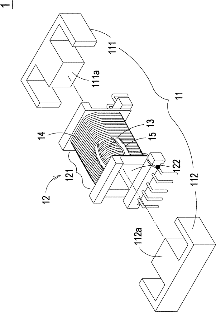
technical field [0001] The invention relates to a transformer structure, especially a transformer structure capable of ensuring electrical safety distances between winding wires and between winding wires and magnetic core groups to avoid flashover caused by high-voltage return wires. Background technique [0002] Transformers are electronic components often used in various electrical equipment to adjust different voltages to the applicable range of electrical appliances. see figure 1 , which is a schematic structural diagram of a traditional transformer. Such as figure 1 As shown, the transformer 1 mainly includes a magnetic core assembly 11 , a bobbin base 12 , a primary winding coil 13 and a secondary winding coil 14 . Wherein, the primary winding 13 and the secondary winding 14 are overlapped and wound in the winding portion 121 of the winding base 12 , and are insulated and separated by, for example, an insulating tape 15 (isolation tape). The magnetic core group 11 ...

Claims


Application Information

Patent Timeline
Patent Type & Authority Patents(China)
IPC IPC(8): H01F30/06H01F27/30H01F27/24H01F27/28
Inventor 田庆相曾祥益
Owner DELTA ELECTRONICS INC
Learn More