
Implementation mode of full-resolution stereo display system

A three-dimensional display and full-resolution technology, applied in optical components, optics, instruments, etc., can solve the problems of easy damage, loss of display resolution, short life, etc., and achieve the effect of simplifying weight and enlarging the acceptable range of sight

Inactive Publication Date: 2010-11-10
TIANMA MICRO ELECTRONICS CO LTD
View PDF4 Cites 6 Cited by
  • Summary
  • Abstract
  • Description
  • Claims
  • Application Information

AI Technical Summary

Problems solved by technology

However, due to the way of the analyzer glasses, it is first necessary to paste a layer of optical film on the display, and this optical film will cause the resolution of the display to be lost by half; while the liquid crystal shutter glasses need a driving circuit to control the switch, and because of the fast closing The execution of the action needs to be synchronized with the display content, so it is necessary to design the liquid crystal lens, drive circuit, infrared receiver and power supply on the liquid crystal shutter glasses, which leads to the following problems: the weight of the liquid crystal shutter glasses makes the observer use for a long time. The discomfort is even worse for people who already wear myopia glasses; the LCD shutter glasses are equipped with a button battery, and are close to the eyes and brain of the person, so the safety makes the observers have scruples, and the rechargeable lithium battery is even more explosive possible; LCD shutter glasses use infrared signals to communicate with the host, and encounter obstacles / external infrared generating devices may be interrupted / interferenced; the price of LCD shutter glasses is high, the life is short, easy to damage, and the overall cost of the user high

Method used


Image

  • Implementation mode of full-resolution stereo display system
  • Implementation mode of full-resolution stereo display system
  • Implementation mode of full-resolution stereo display system

Examples


Embodiment Construction

[0012] In order to make the object, technical solution and advantages of the present invention clearer, the present invention will be further described in detail below in conjunction with the accompanying drawings and embodiments. It should be understood that the specific embodiments described here are only used to explain the present invention, not to limit the present invention.

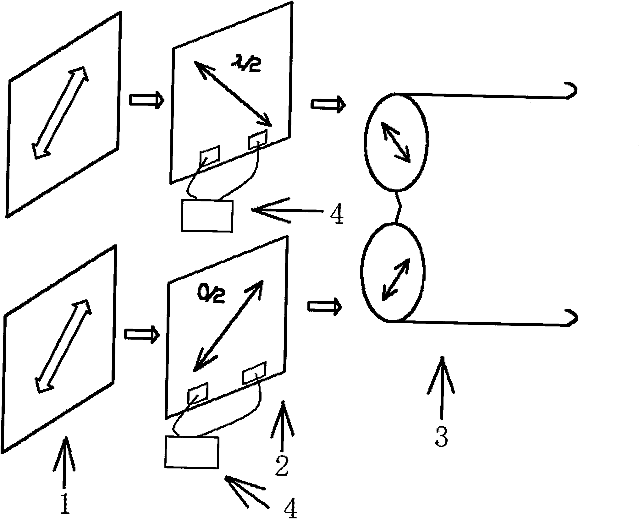
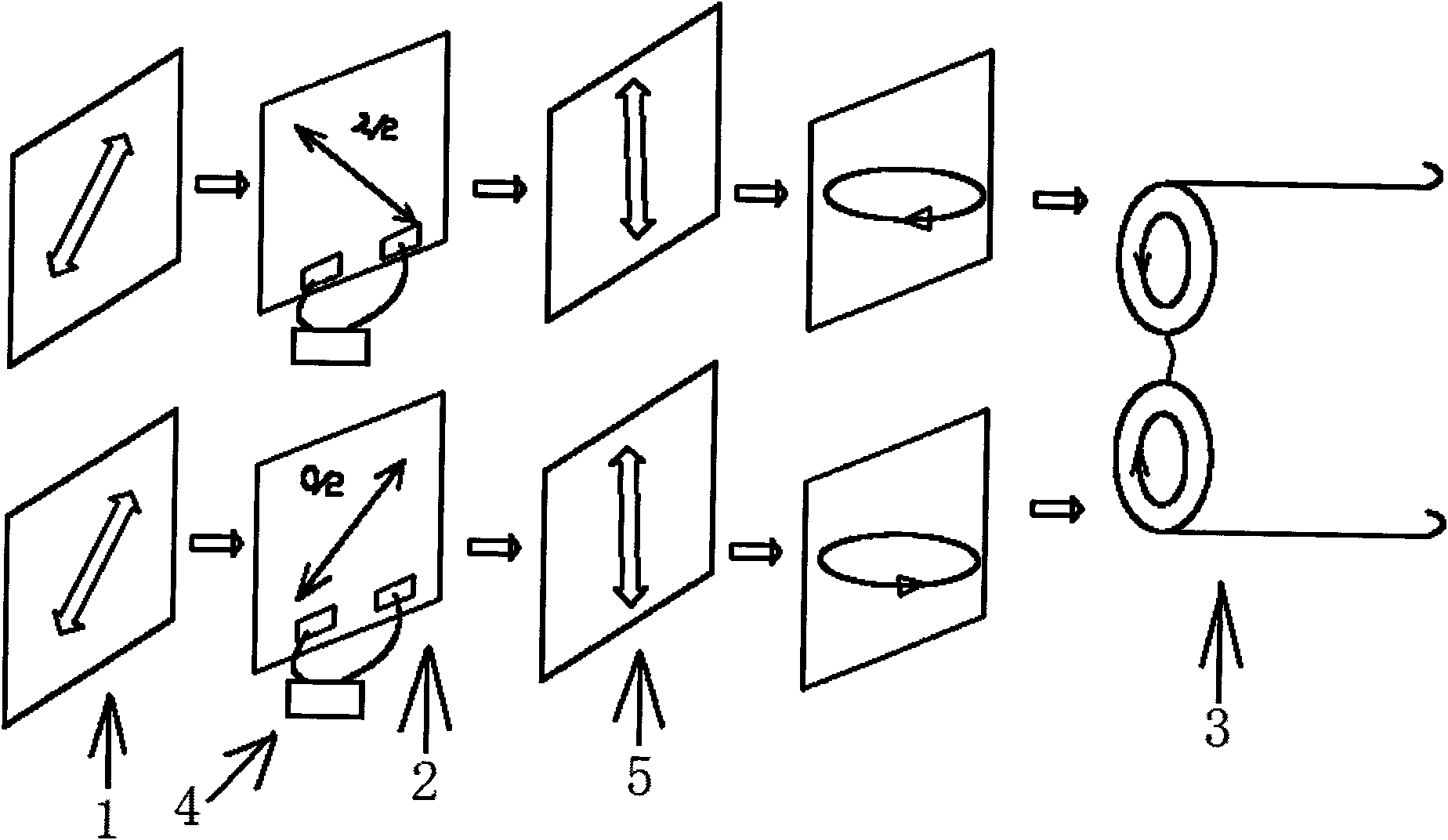
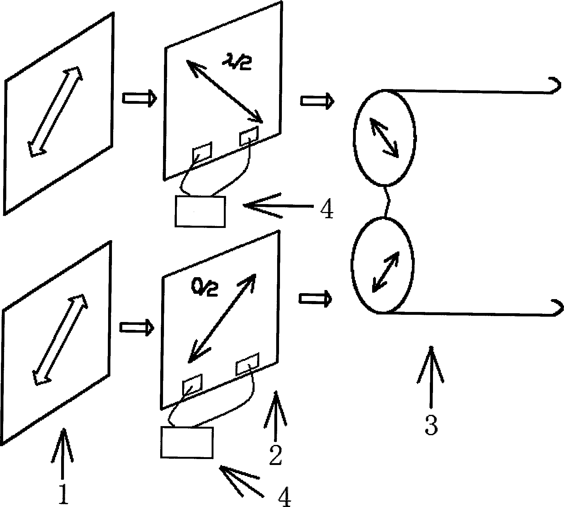
[0013] An implementation of a full-resolution stereoscopic display system is characterized in that a 90-degree twisted TN light valve (shutter) 2 is attached to the frequency doubling display 1, and the TN light valve 2 is connected to a peripheral driver through an FPC. Circuit 4; the drive circuit 4 is synchronized with the signal output by the frequency multiplier display 1, and the TN light valve 2 is controlled by the drive circuit 4, switching with 0λ, λ / 2 phase difference to correspond to the output of the left and right eye images, and then by the detector The polarizing glasses 3 perform p...


PUM


Abstract

The invention discloses an implementation method of a full-resolution stereo display system, which is characterized in comprising the following steps: tightly sticking a TN shutter which is twisted for 90 degrees on a frequency multiplication display, wherein the TN shutter is connected to a peripheral driving circuit through FPC; keeping the signals output by the driving circuit and the frequency multiplication display synchronous, controlling the TN shutter by the driving circuit, and switching at 0lambda, lambda / 2 phase difference so as to correspond the output of the images of left and right eyes; and obtaining a left image and a right image by analyzing through an analyzer. The invention is more suitable for the frequency multiplication display of high refresh rate, adds a lambda / 4 wave plate in optimization design, transfers the linear polarized light into circular polarization, thus the sight receivable range is amplified, an optical film is not arranged, the resolution ratio of the display is not damaged, the weight of the glass is reduced, and a looker feels more comfortable in the process of watching.

Description

【Technical field】 [0001] The invention relates to a stereoscopic display device, in particular to a method for realizing stereoscopic effect applied to a frequency doubling display. 【Background technique】 [0002] The basic principle of the stereoscopic display is to provide two different pictures to the left and right eyes of the human being, and the brain synthesizes the two pictures into an image with a 3D effect. How to provide such a visual environment, there are currently two main ways: first, play two sets of overlapped images on the monitor, and then use the analyzer glasses to separate the two sets of two different images for the left and right eyes, which can be realized The left and right eyes see two different pictures; secondly, use 3D liquid crystal glasses to see different pictures. Opening and closing, with specially processed pictures to get different pictures for each eye, for example, firstly the left eye LCD glasses are opened, and the right eye lens is ...

Claims


Application Information

Patent Timeline
Patent Type & Authority Applications(China)
IPC IPC(8): G02B27/26G02B30/25
Inventor 刘晓林谢佳牛磊陈瑞改
Owner TIANMA MICRO ELECTRONICS CO LTD
Learn More