
Lens actuating device

A lens actuation and lens technology, applied in electromechanical devices, installation, optics, etc., can solve the problems of power consumption, energy waste, large camera module size, cost increase, etc., and achieve the effect of increasing electromagnetic thrust

Inactive Publication Date: 2010-11-10
WAH HONG INDAL CORP
View PDF0 Cites 0 Cited by
  • Summary
  • Abstract
  • Description
  • Claims
  • Application Information

AI Technical Summary

Problems solved by technology

[0006] However, generally speaking, although the lens positioning method can effectively achieve the positioning purpose, it requires the cooperation of multiple components to achieve it, thus resulting in the overall size of the camera module being too large, which limits the development of miniaturization, and also causes cost. Increase
In addition, by continuously supplying power to the coil to achieve the purpose of lens positioning, it will cause power consumption and energy waste

Method used


Image

  • Lens actuating device
  • Lens actuating device
  • Lens actuating device

Examples


Embodiment Construction

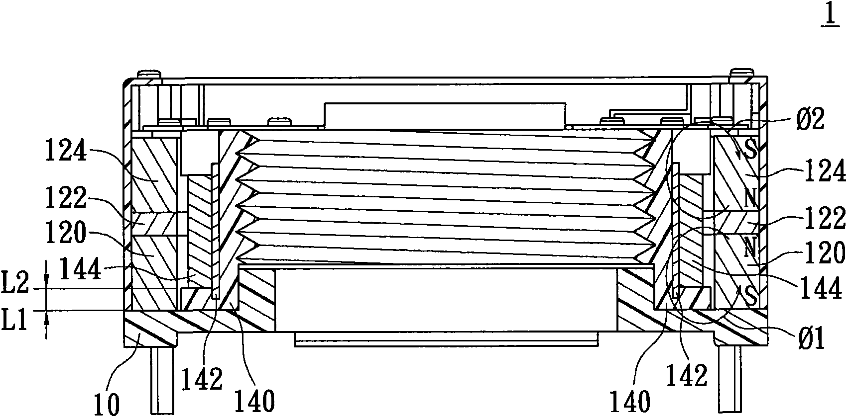
[0034] Please refer to figure 1 and figure 2 , figure 1 is a structural schematic diagram of the first preferred embodiment of the present invention, and figure 2 It is a structural sectional view of the first preferred embodiment of the present invention.

[0035] Such as figure 1 and figure 2 As shown, the lens actuator 1 of the present invention includes a base 10 , a hollow magnetic element 12 , and a lens carrier element 14 . Meanwhile, the hollow magnetic element 12 includes a first hollow magnet 120 , a hollow conductive disc 122 and a second hollow magnet 124 . Wherein, the hollow magnetic disk 122 has a first coupling surface (not marked) and a second coupling surface (not marked), and the first coupling surface is magnetically coupled to the first hollow magnet 120, and the second coupling surface is magnetically coupled to the second coupling surface. Hollow magnet 124. In addition, the first hollow magnet 120 and the second hollow magnet 124 are magnetica...


PUM


Abstract

The invention provides a lens actuating device which comprises a base, a hollow magnetic element, a lens bearing seat, a hollow coil and a magnetic conductive element, wherein the hollow magnetic element is fixed on the base to generate a first magnetic force line loop and a second magnetic force line loop; the lens bearing seat is arranged at the inner edge of the hollow magnetic element, and a sliding gap is alternately formed between the lens bearing seat and the hollow magnetic element; and the magnetic conductive element and the hollow coil are arranged on the lens bearing seat. In the invention, the first magnetic force line loop and the second magnetic force line loop generated by the hollow magnetic element generate a magnetic attraction force with the magnetic conductive element together, and the hollow coil after being electrified and the hollow magnetic element generate an electromagnetic thrust force for pushing the lens bearing seat to displace; and the magnetic conductive element is used for promoting the electromagnetic thrust force so that the magnetic attraction force interacts with the electromagnetic thrust force to displace the lens bearing seat and then locate at a target position.

Description

technical field [0001] The invention relates to a lens actuating device, in particular to an actuating device applicable to lens driving of a miniature camera module. Background technique [0002] In recent years, the trend of handheld devices equipped with camera modules has become more and more common. With the market demand for better performance and smaller size of handheld devices in the product market, camera modules are facing dual requirements of higher image quality and miniaturization. For the improvement of camera quality, on the one hand, it is to increase the pixel. The current market trend of the camera module of the handheld device is from 300,000 pixels of VGA level to gradually increase to megapixels, 2 million pixels, 3 million pixels, and even to a higher level. The four million, five million pixel development. In addition to the improvement of pixels, the clarity of the camera is also more concerned, so the camera module of the handheld device is also de...

Claims


Application Information

Patent Timeline
Patent Type & Authority Applications(China)
IPC IPC(8): G02B7/08H02K33/18
Inventor 刘志坚郭利德
Owner WAH HONG INDAL CORP
Learn More