


Quick Research
Generate reliable direction feasibility study reports for your R&D in just a few steps.

Technical Q&A
Discover and master advanced knowledge NOW. Basics, ideas, possibilities, all at once.

Find Solutions
As an expert in R&D theories, this can generate solutions to your technical problems instantly.

Evaluate Feasibility
Analyze your overall solution with one click, know your potential R&D risks in advance.

Monitor Landscape
Get weekly tech updates, stay abreast of the latest tech innovations and key insights.
Electromagnetic switch for auxiliary-rotation starter
An electromagnetic switch and auxiliary rotation technology, applied in the direction of engine starting, electromagnetic relay, engine components, etc., can solve the problems of deterioration of heat resistance, deterioration of assembly operability, increase of winding space, etc., and achieve good meshing and meshing Good durability and productivity, and the effect of reducing magnetic attraction force
- Summary
- Abstract
- Description
- Claims
- Application Information
AI Technical Summary
Problems solved by technology
Method used
Image


Examples
Embodiment approach 1
[0042] figure 1 It is a configuration diagram showing an electromagnetic switch of the assist swing starter according to Embodiment 1 of the present invention. figure 1 The electromagnetic switch 8 adopts the following structure: that is, it includes: a housing 21, the housing constitutes the outline of the electromagnetic switch 8 and forms a magnetic circuit; a core 18, the core is fixed on one end side of the housing 21; the plunger 11. The above-mentioned plunger is opposed to the above-mentioned core 18 through the gap 23, and protrudes and moves toward the other end side of the above-mentioned housing 21; Inside the case 21, the attracting coil 9 and the holding coil 10 are wound.
[0043] The electromagnetic switch of the auxiliary rotary starter of the present invention is characterized in that a core 26 for magnetic shunting is provided on a part of the inner diameter side of the above-mentioned bobbin 14 at a position that does not contact the plunger 11, and the ...
Embodiment approach 2
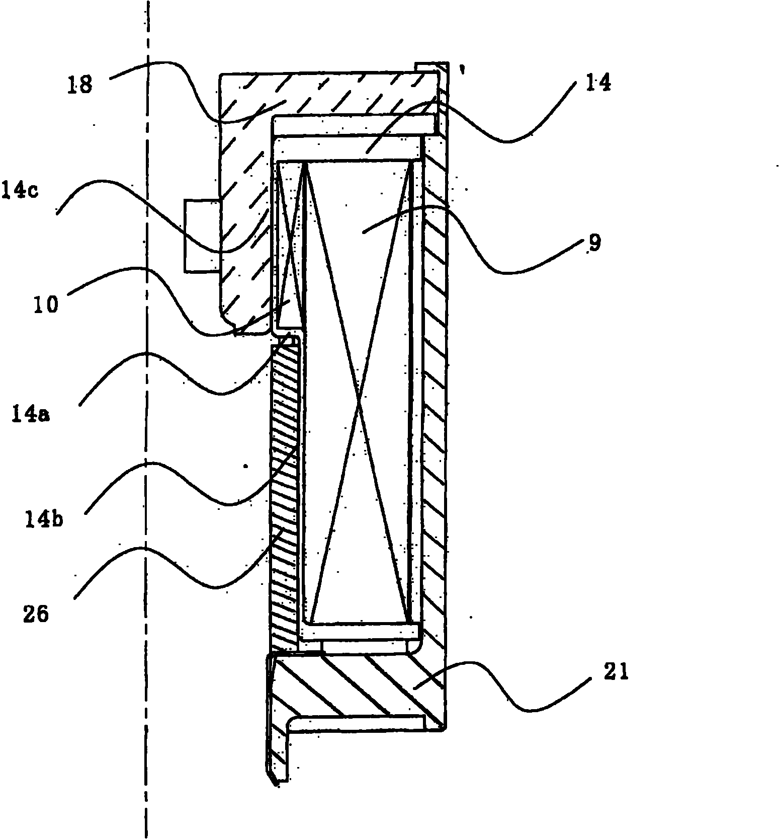
[0055] figure 2 It is a part of the winding structure diagram of Embodiment 2 of this invention. exist figure 2 Among them, the holding coil 10 is only wound on the small diameter portion 14c side of the stepped portion 14a of the bobbin 14, and the difference between the winding outer diameter of the large diameter portion 14b and the holding coil 10 and the coil diameter of the attracting coil 9 is equal to that of the attracting coil 9. At 1 / 2 or less of the coil diameter, the attracting coil 9 is wound in a row around the outer periphery of the holding coil 10 and the large diameter portion of the bobbin 14 .
[0056] According to this structure, the space inside the electromagnetic switch can be used without waste, and the winding operation of the holding coil 10 and the attracting coil 9 becomes easy, and it is possible to provide a low-cost, good assembly, and no damage to the ring gear and pinion. , Electromagnetic switch for auxiliary rotary starter with good mesh...
PUM
 Abstract
Description
Claims
Application Information
 - R&D Engineer
- R&D Manager
- IP Professional
- Industry Leading Data Capabilities
- Powerful AI technology
- Patent DNA Extraction
Browse by: Latest US Patents, China's latest patents, Technical Efficacy Thesaurus, Application Domain, Technology Topic, Popular Technical Reports.
© 2024 PatSnap. All rights reserved.Legal|Privacy policy|Modern Slavery Act Transparency Statement|Sitemap|About US| Contact US: help@patsnap.com