Slag cooler

A slag cooler and slag chip technology, applied in lighting and heating equipment, fluidized bed combustion equipment, combustion methods, etc., can solve the problems of polluted environment, burnout of slag cooler, small flow rate, etc., to reduce environmental pollution, The effect of prolonging the service life and improving work efficiency

Active Publication Date: 2010-11-03
LIAONING BEIFANG ELECTRIC MACHINERY COMPLETE EQUIP
View PDF0 Cites 0 Cited by
  • Summary
  • Abstract
  • Description
  • Claims
  • Application Information

AI Technical Summary

Problems solved by technology

[0002] The existing cylindrical inner and outer walls of the slag cooler are supported by steel bars spirally wound on the inner wall, so that a cooling water interlayer is formed between the two walls. Since the cooling water is limited by the steel bars, it can only flow along the spiral Channel flow, the flow rate of water is slow and the flow rate is small, which cannot meet the needs of slag cooling. The temperature of the slag entering from the slag inlet is 1100-1200°C, and the temperature of the slag coming out of the slag outlet of the slag cooler is as high as 350-400°C. It needs natural cooling before it can be loaded and transported away, which pollutes the environment; and because of the slow flow rate of cooling water, the water is often vaporized before reaching the slag inlet of the slag cooler, causing the inner wall of the slag cooler to be burned out, affecting the normal production

Method used


Image

  • Slag cooler
  • Slag cooler
  • Slag cooler

Examples


Embodiment Construction

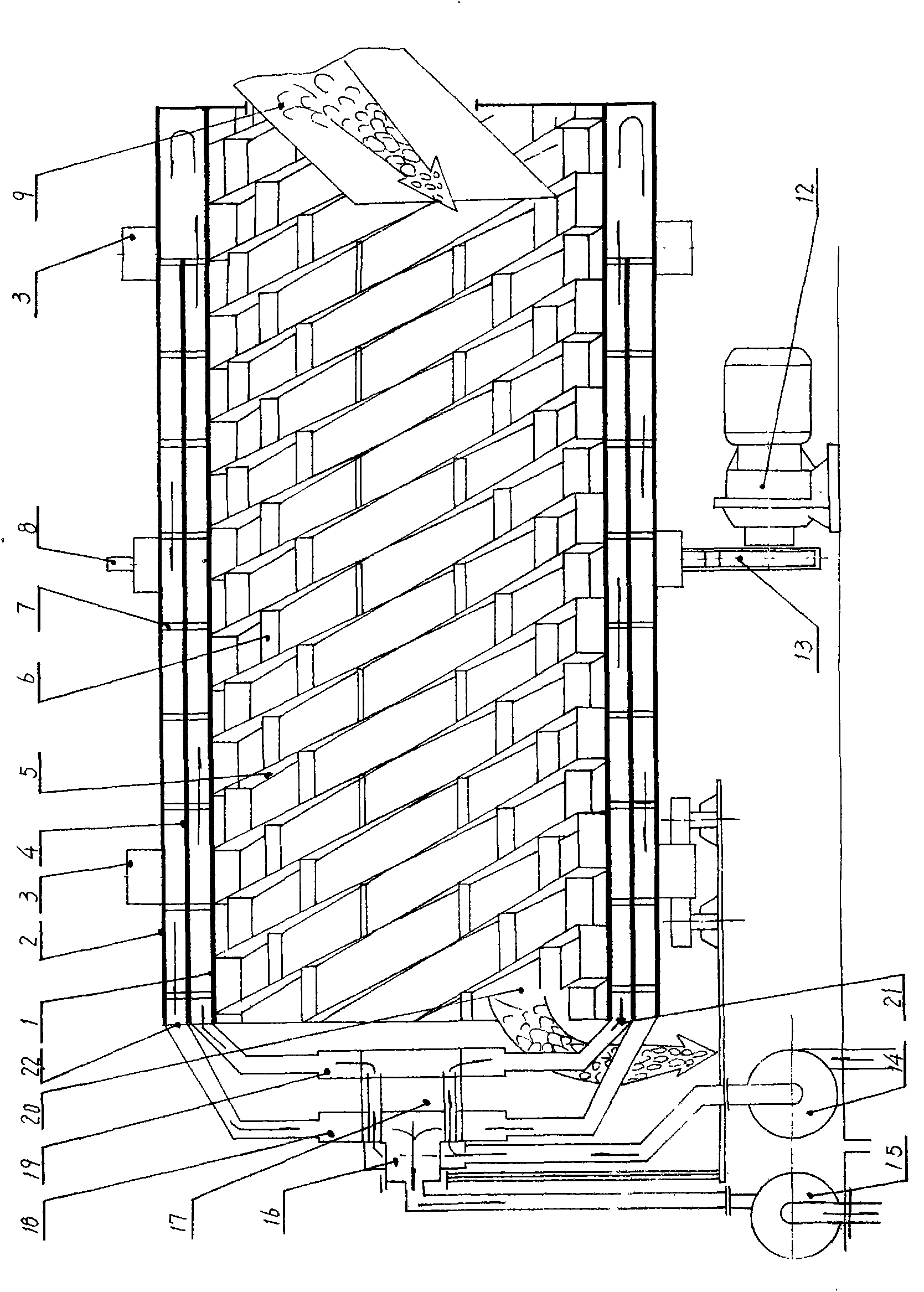
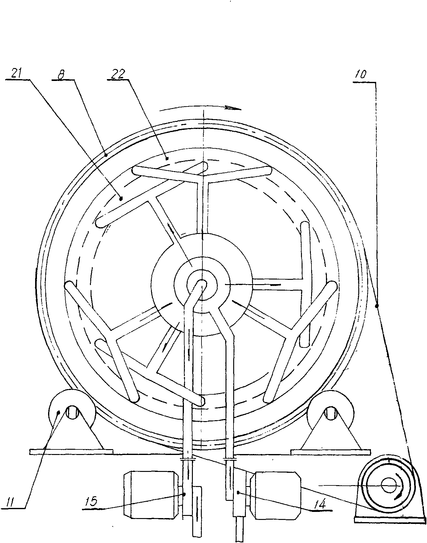
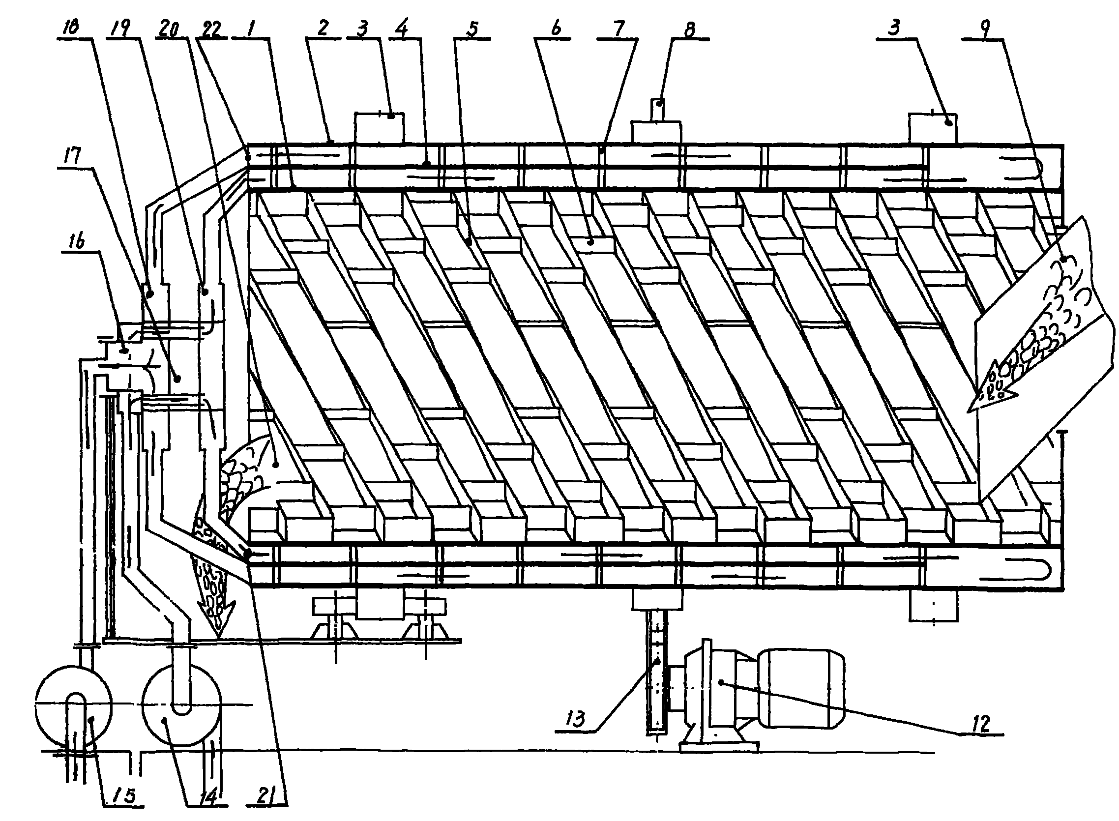
[0008] refer to figure 1 , 2 , the cylindrical barrel body includes an inner barrel wall 1 and an outer barrel wall 2, a cooling water interlayer is formed between the inner and outer barrel walls, and slag guide pieces 5 arranged in a spiral shape are welded on the inner side of the inner barrel wall, and the adjacent spiral Several partitions 6 are welded on the inner cylinder wall between the arranged slag guide sheets, and several small grids are formed between the partition boards and the slag guide sheets. There is a slag inlet 9 at one end of the cylinder body, and a slag discharge port 20 at the other end. Two tracks 3 surrounding the barrel body are fixed on the outer wall of the barrel body, and the track is placed on the track supporting wheel 11 of the support base, and a large sprocket 8 is also installed on the outer wall, and the large sprocket is driven by the chain 10 and the reducer 12 The sprocket 13 is connected, and there is also an inlet water pump 14 an...


PUM


Abstract

The invention relates to a slag cooler for cooling slag of a circulating fluidized bed boiler of a power plant, mainly designed to solve the problems of poor cooling effect and easy burnout of the traditional slag cooler. The slag cooler comprises an inner cylinder wall, an outer cylinder wall, a cooling water interlayer, a slag guide sheet, a slag inlet, a slag outlet end, a track, a track supporting wheel, a large sprocket, a water inlet pump and a water pumping pump, wherein a partition wall is arranged between the inner cylinder wall and the outer cylinder wall, a small support upright column is respectively arranged between the partition wall and the inner cylinder wall as well as between the partition wall and the outer cylinder wall, an inner sealing head and an outer sealing head are also arranged between the partition wall and the inner cylinder wall as well as between the partition wall and the outer cylinder wall, a pipeline is arranged on the water inlet pump and is connected with an inner ring of a water separator, the inner ring is provided with a water outlet and is connected with an outer ring in a sliding and sealing mode, a water outlet pipe is arranged on the outer ring and is connected with the inner sealing head, a pipeline is arranged on the water pumping pump and is connected with an inner ring of a water collector, a water inlet is arranged on the inner ring of the water collector, the external of the inner ring of the water collector is connected with the outer ring of the water collector in the sliding and sealing mode, and a water inlet pipe is arranged on the outer ring and is connected with the outer sealing head. The invention has the advantages of good cooling effect and long service life.

Description

Technical field: [0001] The invention relates to a slag cooler for cooling the slag of a circulating fluidized bed boiler in a power plant. Background technique: [0002] The existing cylindrical inner and outer walls of the slag cooler are supported by steel bars spirally wound on the inner wall, so that a cooling water interlayer is formed between the two walls. Since the cooling water is limited by the steel bars, it can only flow along the spiral The channel flows, the flow rate of water is slow and the flow rate is small, which cannot meet the needs of slag cooling. The temperature of the slag entering from the slag inlet is 1100-1200°C, and the temperature of the slag coming out of the slag outlet of the slag cooler is as high as 350-400°C. It needs natural cooling before it can be loaded and transported away, polluting the environment; moreover, due to the slow flow of cooling water, the water is often vaporized before reaching the slag inlet of the slag cooler, causi...

Claims


Application Information

Patent Timeline
Patent Type & Authority Applications(China)
IPC IPC(8): F23J1/06F23C10/24
Inventor 温巨国
Owner LIAONING BEIFANG ELECTRIC MACHINERY COMPLETE EQUIP
Why Eureka
Try Eureka