Ball-valve operated fuel injector

A fuel injector and injector body technology, which can be used in fuel injection devices, charging systems, machines/engines, etc., can solve the problem of high manufacturing costs

Inactive Publication Date: 2010-10-27
ROBERT BOSCH GMBH
View PDF2 Cites 10 Cited by
  • Summary
  • Abstract
  • Description
  • Claims
  • Application Information

AI Technical Summary

Problems solved by technology

Such a fuel injector is substantially more expensive to manufacture than a fuel injector configured as a spherical valve element

Method used


Image

  • Ball-valve operated fuel injector
  • Ball-valve operated fuel injector
  • Ball-valve operated fuel injector

Examples


Embodiment Construction

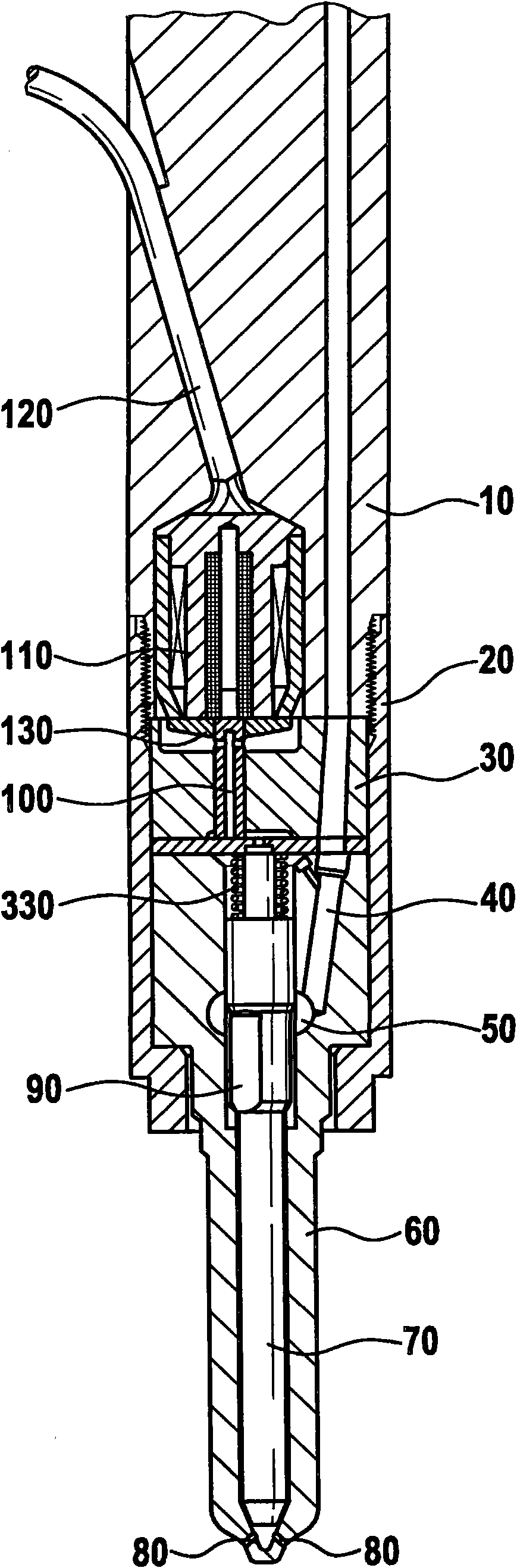
[0022] figure 1 A fuel injector according to the prior art is shown in , which is provided with a conventional valve needle.

[0023] The nozzle holder 10 includes a high pressure line 40 filled with fuel, such as diesel fuel. The nozzle holder 10 also includes an electromagnet 110 which is controlled via an electrical connection 120 . Electromagnet 110 is connected to a valve seat 130 and to an injection valve part 100 . If current is passed through electromagnet 110 , injection valve member 100 is moved along the first axis and the connection to control chamber 330 is released. In this way, the fuel located in the control chamber 330 flows out via the valve 100 and a suitable connection. The pressure in the control chamber 330 drops as a result of the outflow of fuel from the control chamber 330 .

[0024] Located in the lower part of the fuel injector is a nozzle body 60 , which includes an injection valve element 70 , which is preferably designed as a needle, and into ...


PUM


Abstract

The invention relates to a fuel injector comprising a nozzle retainer (10) or an injector body (20), a valve body (30) and a nozzle body (60), in which a preferably needle-shaped injection valve member (70) is arranged to be vertically movable, said member releasing or closing at least one injection port (80) leading to a combustion chamber of an internal combustion engine depending on the pressure relief of or the pressure load on a control chamber (330). The invention is characterized in that a valve comprising a preferably ball-shaped valve element (200) is arranged in the nozzle retainer (10) or in the injector body (20) for the pressure relief of the control chamber (330).

Description

Background technique [0001] Modern internal combustion engines, especially diesel engines, use injection systems in which a high-pressure pump brings the fuel to a high pressure level. A high-pressure accumulator bank (common rail) is charged with fuel, which is permanently under pressure during engine operation, ie is charged with a system pressure level generated by the high-pressure pump. Several high-pressure lines branch off from the high-pressure accumulator bank, which ensure the supply of fuel to the engine cylinders. The fuel delivered via the high-pressure line is injected into the combustion chambers of the cylinders of the internal combustion engine via fuel injectors. [0002] In common rail injection systems, the injection process in the combustion chamber of the internal combustion engine is decoupled from the pressure in the high-pressure accumulator bank (common rail). The timing and amount of fuel injection can thus be controlled by the engine electronics. ...

Claims


Application Information

Patent Timeline
Patent Type & Authority Applications(China)
IPC IPC(8): F02M47/02F02M63/00
CPCF02M63/0015F02M47/027F02M63/0043
Inventor M·施内尔
Owner ROBERT BOSCH GMBH
Why Eureka
Try Eureka