
Measurement gap configuration method and device of multi-carrier polymerization system

A technology of multi-carrier aggregation and measurement gap, applied in the field of communication, can solve problems such as the inability to meet this demand, and achieve the effects of enhancing system capacity, improving data transmission quality, and enhancing system transmission performance

Active Publication Date: 2010-10-27
DATANG MOBILE COMM EQUIP CO LTD
View PDF3 Cites 90 Cited by
  • Summary
  • Abstract
  • Description
  • Claims
  • Application Information

AI Technical Summary

Problems solved by technology

This demand can no longer be met on the bandwidth of 20MHz

Method used


Image

  • Measurement gap configuration method and device of multi-carrier polymerization system
  • Measurement gap configuration method and device of multi-carrier polymerization system
  • Measurement gap configuration method and device of multi-carrier polymerization system

Examples


Embodiment 1

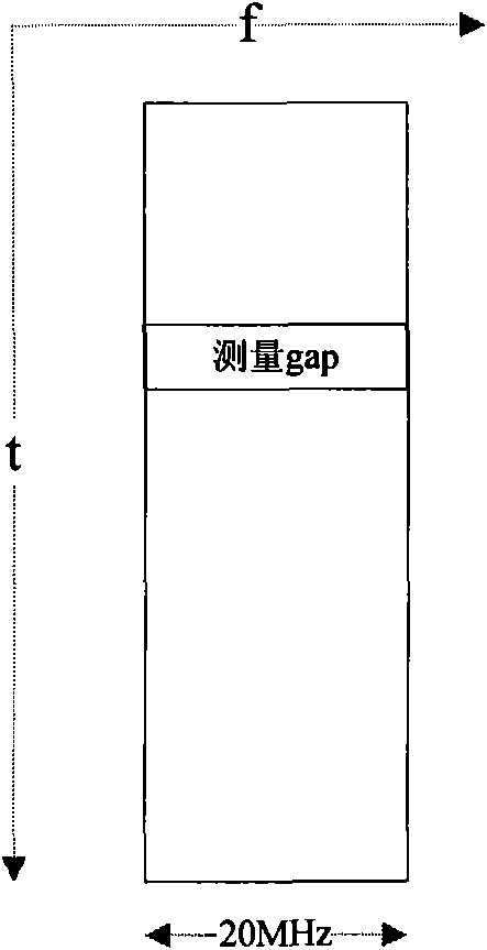
[0067] see Figure 7 As shown, the eNB is only configured to measure the gap on f1. At this time, the eNB may notify the UE to configure the measurement gap for the component carrier f1 through dedicated RRC signaling, but not configure the measurement gap for the component carrier f2 and f3. In this way, after receiving the RRC signaling, the UE configures the measurement gap on f1 according to the content of the signaling, and continues to work on f2 and f3. When the measurement gap is not entered, the UE continues to perform CA transmission on the 3 carriers; when the measurement gap is entered, the UE uses the receiver 1 corresponding to f1 to measure on the different frequency f4 or f5, and the corresponding frequency of f2 and f3 Receiver 2 and receiver 3 continue to perform CA transmission, as shown in Figure 5, only during the measurement gap of f1, CA transmission cannot be performed, and transmission at other times is not affected by the measurement, which can impro...

Embodiment 2

[0069] see Figure 8 As shown, the eNB only configures the measurement gap on f2 and selects to configure the measurement gap only on f2. In this case, f2 can be measured by f4 during CA transmission, and f5 can be measured during gap. It can also increase the overall data transfer rate. Configuring gap measurement for f3 alone is similar to configuring gap measurement for f2 alone.

Embodiment 3

[0071] Such as Figure 9 As shown, the measurement gap is configured on both f2 and f3. The eNB configures and measures the gap for f1 and f2 respectively, and the two configurations may be the same or different. In this case, within the measurement gap, the UE can use the receiver corresponding to f1 to measure f4, and use the receiver corresponding to f2 to measure f5, so as to achieve the purpose of measuring two frequency points at the same time and improve the efficiency of measurement. However, some data transfer rate may be lost at this time.


PUM


Abstract

The invention discloses a measurement gap configuration method and a device of a multi-carrier polymerization system. The method comprises the following steps that: according to the measurement capability of a user terminal reported by the user terminal and the frequency points of a different frequency or a different system to be measured, the measurement gap configuration information of the userterminal is determined, and the measurement gap configuration information instructs to measure the different frequency or the different system to partial or all working member carriers of the user terminal; and the measurement gap configuration information is sent to the user terminal, and the measurement gap configuration information is used for providing the measurement of the different frequency or the different system to the user terminal when in multi-carrier polymerization transmission. The embodiment of the invention respectively configures measurement gaps to partial or all member carriers of the user terminal in a multi-carrier polymerization system, so that the user terminal does not need to stop CA transmission when entering the measurement gaps, thereby improving the data transmission quality and enhancing the transmission performance of the system and the system capacity.

Description

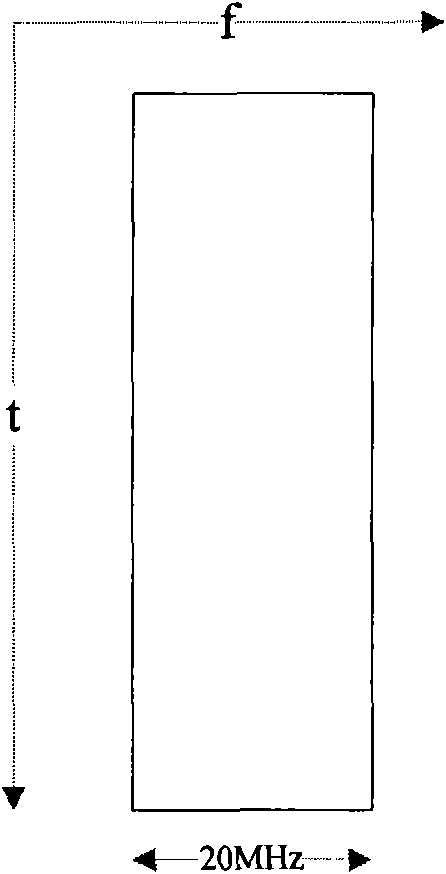
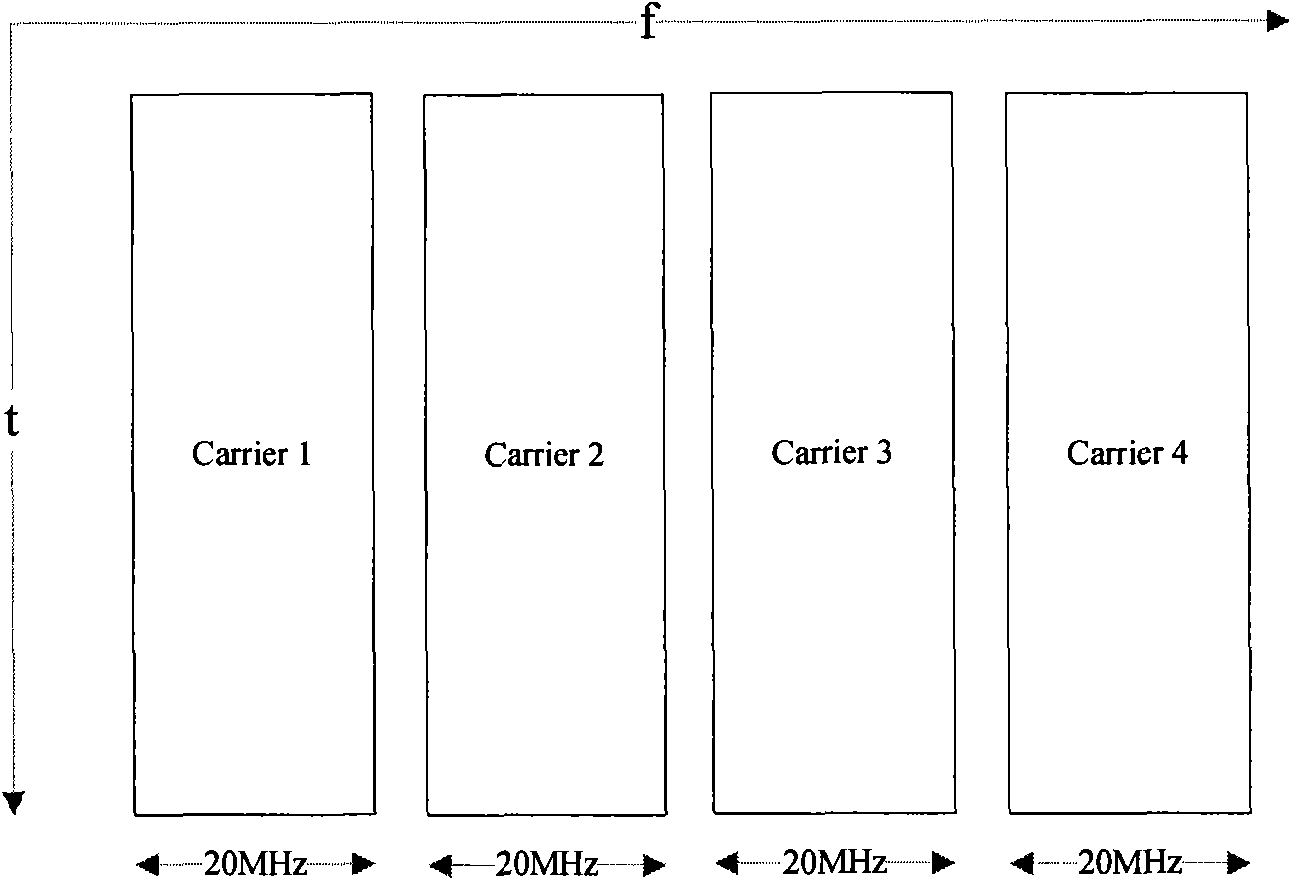
technical field [0001] The present invention relates to the field of communication technologies, in particular to a method and device for configuring measurement gaps in a multi-carrier aggregation system. Background technique [0002] In the long-term evolution (LTE) system and previous wireless communication systems, there can only be one carrier in a cell, and the maximum bandwidth in the LTE system is 20MHz, such as figure 1 shown. [0003] In the advanced long-term evolution (LTE Advanced, LTE-A) system, the peak rate of the system is greatly improved compared with LTE, and it is required to reach 1 Gbps in the downlink and 500 Mbps in the uplink. This demand can no longer be met on the bandwidth of 20MHz. The LTE-A system introduces carrier aggregation (Carrier Aggregation, CA) technology, that is, in the same cell, a plurality of continuous or discontinuous carriers are gathered together to serve the user terminal (UE) at the same time when needed, so as to provide ...

Claims


Application Information

Patent Timeline
IPC IPC(8): H04W28/18H04W36/00H04W72/04
Inventor 梁靖彦楠高卓
Owner DATANG MOBILE COMM EQUIP CO LTD
Learn More