
Supporting mechanism

A support mechanism and support device technology, which is applied in the direction of supporting machines, testing of machine/structural components, mechanical equipment, etc., can solve the problems of not being able to ensure the same center height of drill pipes, and not being able to adapt to slender rods, etc., to achieve saving Adjustment time, adjustment cost reduction, effect of simplifying adjustment process

Inactive Publication Date: 2010-10-13
BEIJING SANY HEAVY MASCH CO LTD
View PDF6 Cites 5 Cited by
  • Summary
  • Abstract
  • Description
  • Claims
  • Application Information

AI Technical Summary

Problems solved by technology

At the same time, in the prior art, the slender rods, especially the drill pipes, are supported by a closed slewing support device. However, this support structure cannot be adapted to slender rods of different diameters or specifications.
When using this kind of closed slewing support device, it cannot ensure that each section of the drill pipe remains at the same center height position, so it is necessary to adjust the center height position of the drill pipe through a special up and down position adjustment device according to the diameter of the drill pipe. make adjustments

Method used


Image

  • Supporting mechanism
  • Supporting mechanism
  • Supporting mechanism

Examples


Embodiment Construction

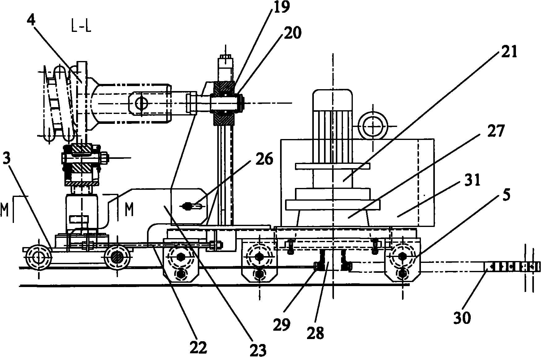
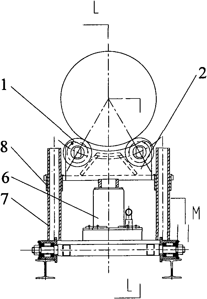
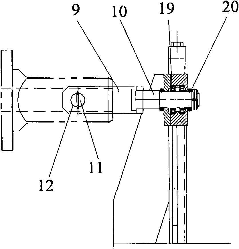
[0027]figure 1 A support mechanism according to the invention is shown, wherein the mechanism has support means and push-pull means. exist figure 1 The support device can be seen on the left side, which has: at least two supporting wheels 1, a flange 4 for openly carrying an elongated rod, wherein in a preferred embodiment of the invention, the elongated rod It is a drill pipe; the supporting roller frame 2 is used to carry the supporting roller 1; the lifting device is used to lift the supporting roller frame 2; the guiding structure is used to guide the lifting movement of the supporting roller frame 2; and it can run on the track The chassis trolley 3 is used to carry lifting equipment and guiding structures. exist figure 1 The right side of the shows the push-pull device, which has a push-pull head structure for pushing and pulling elongated rods; a push-pull head height adjustment structure for adjusting the height of the push-pull head structure; The push-pull trolley...


PUM


Abstract

The invention relates to a supporting mechanism, which is used for supporting a slender rod piece. The slender rod piece is provided with a centre rod. The supporting mechanism is provided with a supporting device and a push-pull device. The supporting device comprises supporting wheels (1) which are arranged in pairs, and the supporting wheels can lift so as to openly bear the centre rod; and the push-pull device comprises a push-pull head structure which is connected with the centre rod so as to push and pull the centre rod and can lift. The supporting mechanism can flexibly adapt to slender rod pieces with different diameters or specifications.

Description

technical field [0001] The invention relates to a support mechanism for an elongated bar, which has support means and push-pull means. In addition, the present invention also relates to a detection device having the support mechanism of the above-mentioned type. Background technique [0002] The diameter and width of the front flange of the drill pipe of the rotary drilling rig series are various, and the square head of the front end of the drill pipe usually has three sizes: square 220, square 200, and square 150. When using different sizes of drill pipes, the size of the flange will also change. Meanwhile, in the prior art, the slender rods, especially the drill rods, are supported by a closed slewing support device, however, this support structure cannot be adapted to slender rods of different diameters or specifications. When using this kind of closed slewing support device, it cannot ensure that each section of the drill pipe remains at the same center height position...

Claims


Application Information

Patent Timeline
IPC IPC(8): F16M11/24F16M11/04G01M19/00G01M99/00
Inventor 孙卫波周鸣放苏杰
Owner BEIJING SANY HEAVY MASCH CO LTD
Learn More