Method for configuring bus bar of aluminum electrolytic bath

A busbar configuration and electrolytic cell technology, which is applied in the field of busbar current configuration around large-scale aluminum electrolytic cells, can solve the problems of production operation hazards, poor cell stability, and excessive local magnetic field of electrolytic cells, so as to save bus consumption and improve Design and production requirements, the effect of meeting stability requirements

Inactive Publication Date: 2010-10-13
GUIYANG AL-MG DESIGN & RES INST
View PDF7 Cites 11 Cited by
  • Summary
  • Abstract
  • Description
  • Claims
  • Application Information

AI Technical Summary

Problems solved by technology

If the original busbar design around the tank is adopted, it cannot well meet the design requirements of the electrolytic tank magnetic field, which will cause the local magnetic field of the electrolytic tank to be too large and the stability of the tank is not good, which not only brings great harm to the production operation, but also cannot produce good results. economic benefits

Method used


Image

  • Method for configuring bus bar of aluminum electrolytic bath
  • Method for configuring bus bar of aluminum electrolytic bath
  • Method for configuring bus bar of aluminum electrolytic bath

Examples


Embodiment 1

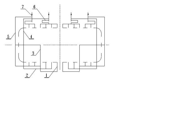
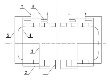
[0010] Example 1: During the production of the electrolytic cell, the direct current enters the four column busbars 7 on the power supply side of the cell from the upstream electrolyzer, and the current enters the anode busbar of the upper structure of the cell through the four column busbars 7 of the same current, and then distributes to 12 sets of anodes, and then flow through the molten electrolyte layer, aluminum liquid layer in the tank, 12 sets of cathode carbon blocks, and 12 sets of cathode steel rods, and then pass through 12 sets of cathode soft busbars welded with cathode steel rods on the power supply side 1 Lead in the cathode busbar 2 on the power supply side, and then flow into 2 busbars at the bottom of the zigzag groove 3, 2 through busbars at the bottom of the groove 4, 2 busbars at the side of the groove 5, and 2 busbars at the bottom of the zigzag groove 3 respectively merge into two busbars on the side of the tank, and then pass through the busbars 4 and bu...


PUM


Abstract

The invention discloses a method for configuring a bus bar of an aluminum electrolytic bath. The current in the electrolytic bath flows out from a power-in bus bar through a negative soft bus bar (1) to a zigzag bottom bus bar (3), a bottom through bus bar (4) and a side bus bar (5) respectively though a power-in negative bus bar, then enters a side bus bar through the zigzag bottom bus bar (3) and finally enters 4 pillar bus bars (7) of a downstream bath through the bottom through bus bar (4) and the side bus bar (5) respectively; and the current also flows out from a power-out bus bar through the negative soft bus bar (1) to the 4 pillar bus bars (7) of the downstream bath through a power-out negative bus bar (6). In the method, in an overall consideration of technology and economy and based on the configuration form of negative and positive pole numbers of the whole bath and the power-in way, a scheme for the magnetic field compensation of large aluminum electrolytic baths is more rationally designed to achieve a good magnetic field compensation effect and save the using amount of the bus bar around the baths so as to overcome the adverse factors in the conventional electrolytic baths.

Description

technical field [0001] The invention relates to the technical field of a current supply device for an aluminum electrolytic cell, in particular to a method for arranging bus current around a large aluminum electrolytic cell. Background technique [0002] With the development of my country's aluminum industry production technology, the current intensity of the series of modern large-scale aluminum electrolytic cells is increasing day by day, and the electromagnetic force generated by the interaction between the magnetic field generated by the production current of the electrolytic cell and the melt current in the electrolytic cell makes the melt in the cell The systemic circulation is accelerated, causing the aluminum liquid level to rise, deflect and fluctuate, and may even affect the normal production of the electrolytic cell. Therefore, in order to achieve the stability of the ferrofluid in the electrolytic cell, it is more important to design the busbar around the cell, wh...

Claims


Application Information

Patent Timeline
IPC IPC(8): C25C3/16
Inventor 刘忠琼颜非亚
Owner GUIYANG AL-MG DESIGN & RES INST
Why Eureka
Try Eureka