
Over-voltage protection device

A protection device and overvoltage technology, applied in the direction of protection against overvoltage, etc., can solve problems such as computer system failure, motherboard failure, etc.

Active Publication Date: 2010-10-06
XINJIANG BAZHOU ELECTRIC POWER
View PDF0 Cites 3 Cited by
  • Summary
  • Abstract
  • Description
  • Claims
  • Application Information

AI Technical Summary

Problems solved by technology

At this time, the motherboard will malfunction, causing the computer system to fail to operate.

Method used


Image

  • Over-voltage protection device
  • Over-voltage protection device
  • Over-voltage protection device

Examples


Embodiment Construction

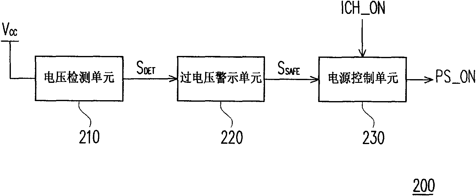
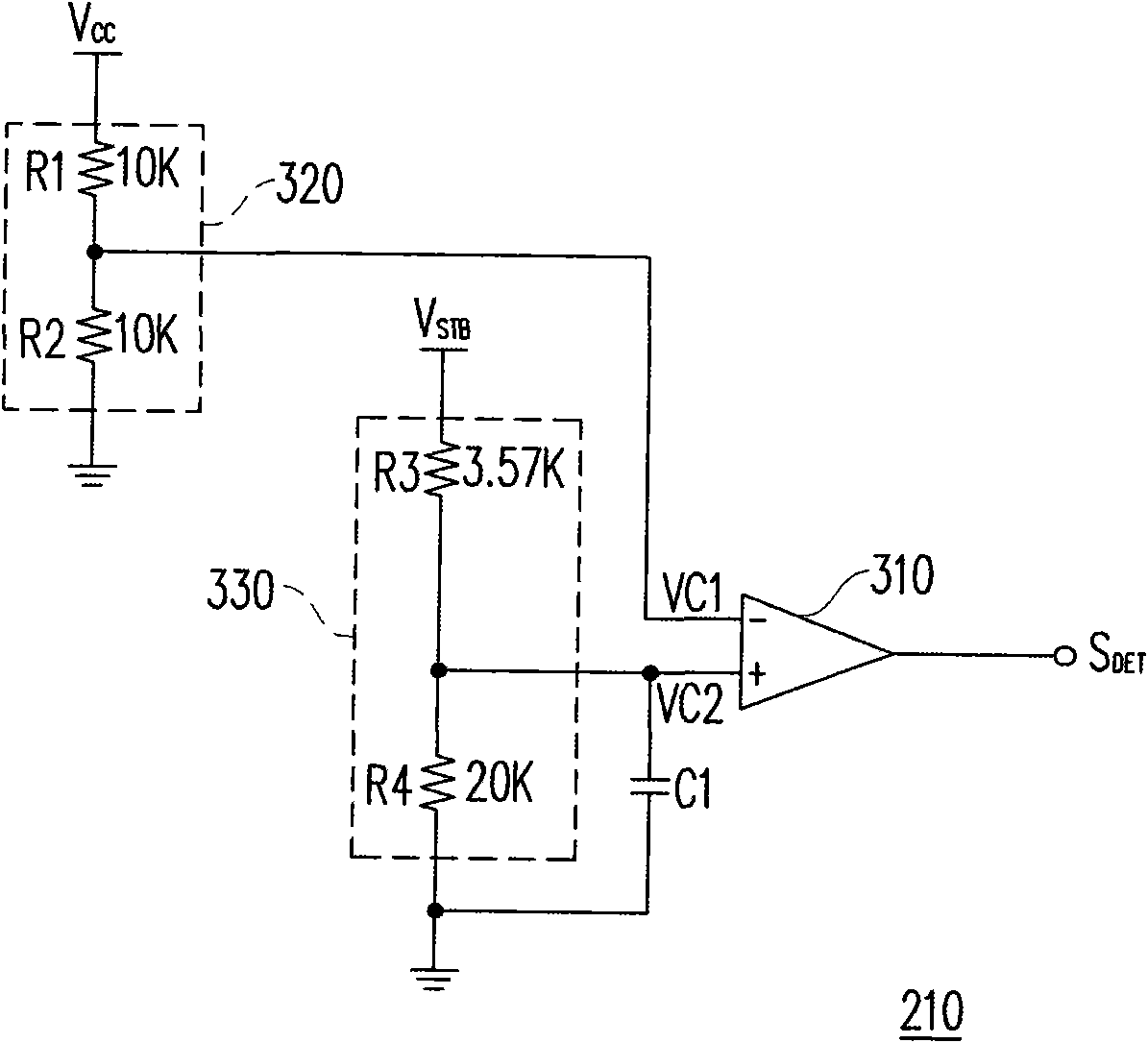
[0033] figure 2 It is a system schematic diagram of an overvoltage protection device according to an embodiment of the present invention. Please refer to figure 2 , The overvoltage protection device 200 includes a voltage detection unit 210, an overvoltage warning unit 220, and a power control unit 230. The voltage detection unit 210 is coupled to the system voltage Vcc to detect whether the system voltage Vcc is too high, which may cause the chip on the motherboard to burn. Here, a preset voltage can be set as the safe upper limit of the system voltage Vcc, and the preset voltage can be less than or equal to the maximum withstand voltage of the chip on the motherboard. The voltage detection unit 210 can compare the system voltage Vcc with a preset voltage to detect whether the system voltage Vcc is too high. When the system voltage Vcc is greater than the preset voltage, the voltage detection unit 210 outputs the first logic (for example, low logic voltage level) detection ...


PUM


Abstract

The invention relates to an over-voltage protection device which comprises a voltage detection unit, an over-voltage warning unit and a power control unit. When a system voltage is greater than a preset voltage, the voltage detection unit outputs a first logic or outputs a second logic; the over-voltage warning unit is coupled with the voltage detection unit and generates a voltage safety signal according to the output of the voltage detection unit; when the voltage detection unit outputs the first logic, the over-voltage warning unit carries out over-voltage warning; the power control unit is coupled with the over-voltage warning unit and receives a power driving signal; and when the voltage detection unit outputs the second logic and the power driving signal is enabled, the power control unit outputs a power enabling signal with a fourth logic according to the voltage safety signal so as to start a power supply, or the power control unit outputs a power enabling signal with a third logic so as to stop the power supply.

Description

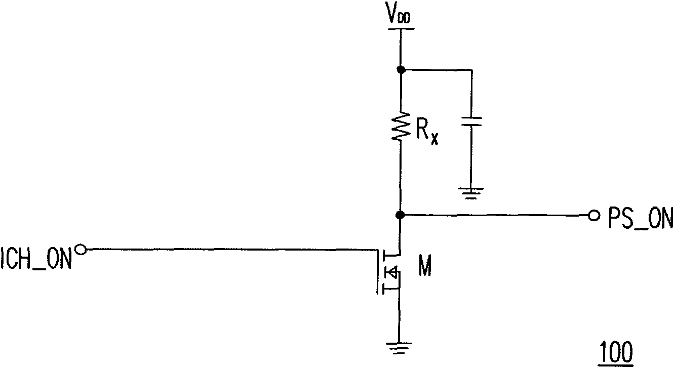
Technical field [0001] The invention relates to an overvoltage protection device, in particular to an overvoltage protection device capable of turning off a power supply. Background technique [0002] In a computer system, multiple system voltages required by the motherboard are generally generated by a power supply. The chip on the motherboard only starts to operate after receiving the system voltage. The current control method of the power supply is that the standby chip on the motherboard detects whether the user is booting and generates a power enable signal to the power supply according to this. The standby chip generates the power enable signal through the voltage control unit . After receiving the power enable signal, the power supply starts to run to generate multiple system voltages. [0003] figure 1 The circuit diagram of the traditional power control unit. The standby chip here takes the South Bridge chip as an example. When the user does not press the power button,...

Claims


Application Information

Patent Timeline
Patent Type & Authority Applications(China)
IPC IPC(8): H02H3/20
Inventor 蔡育生刘士豪
Owner XINJIANG BAZHOU ELECTRIC POWER
Learn More