Eureka AIR delivers breakthrough ideas for toughest innovation challenges, trusted by R&D personnel around the world.

Bottom rotary switching mechanism

A switching mechanism and waterway switching technology, applied in the direction of mechanical equipment, engine components, pipe supports, etc., can solve the problems of inconvenient switching, achieve the effect of convenient switching, ensure the guiding performance, and increase the switching machine

Inactive Publication Date: 2010-10-06
XIAMEN SOLEX HIGH TECH IND CO LTD
View PDF5 Cites 11 Cited by
  • Summary
  • Abstract
  • Description
  • Claims
  • Application Information

AI Technical Summary

Problems solved by technology

[0003] The present invention provides a bottom rotation switching mechanism, which overcomes the disadvantage of inconvenient switching in the switching mechanism in the background technology

Method used


Image

  • Bottom rotary switching mechanism
  • Bottom rotary switching mechanism
  • Bottom rotary switching mechanism

Examples


Embodiment Construction

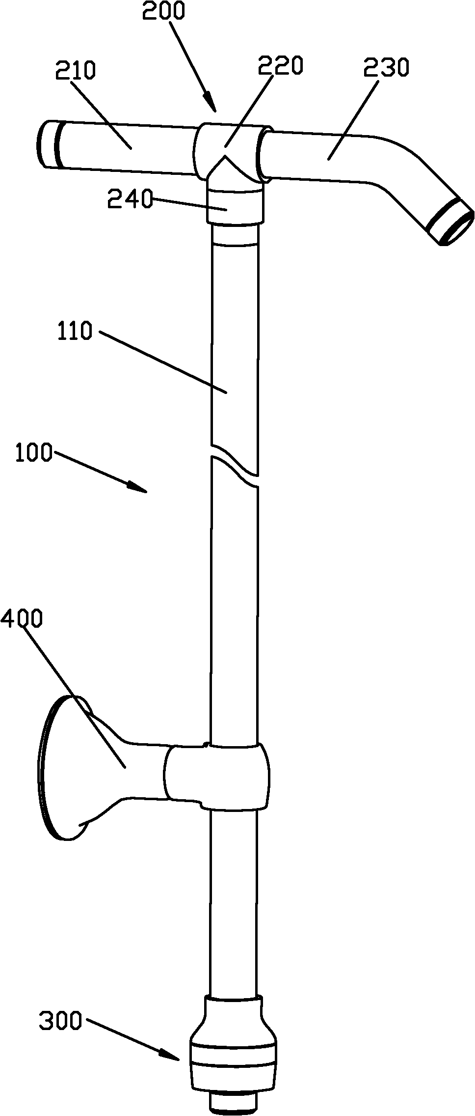
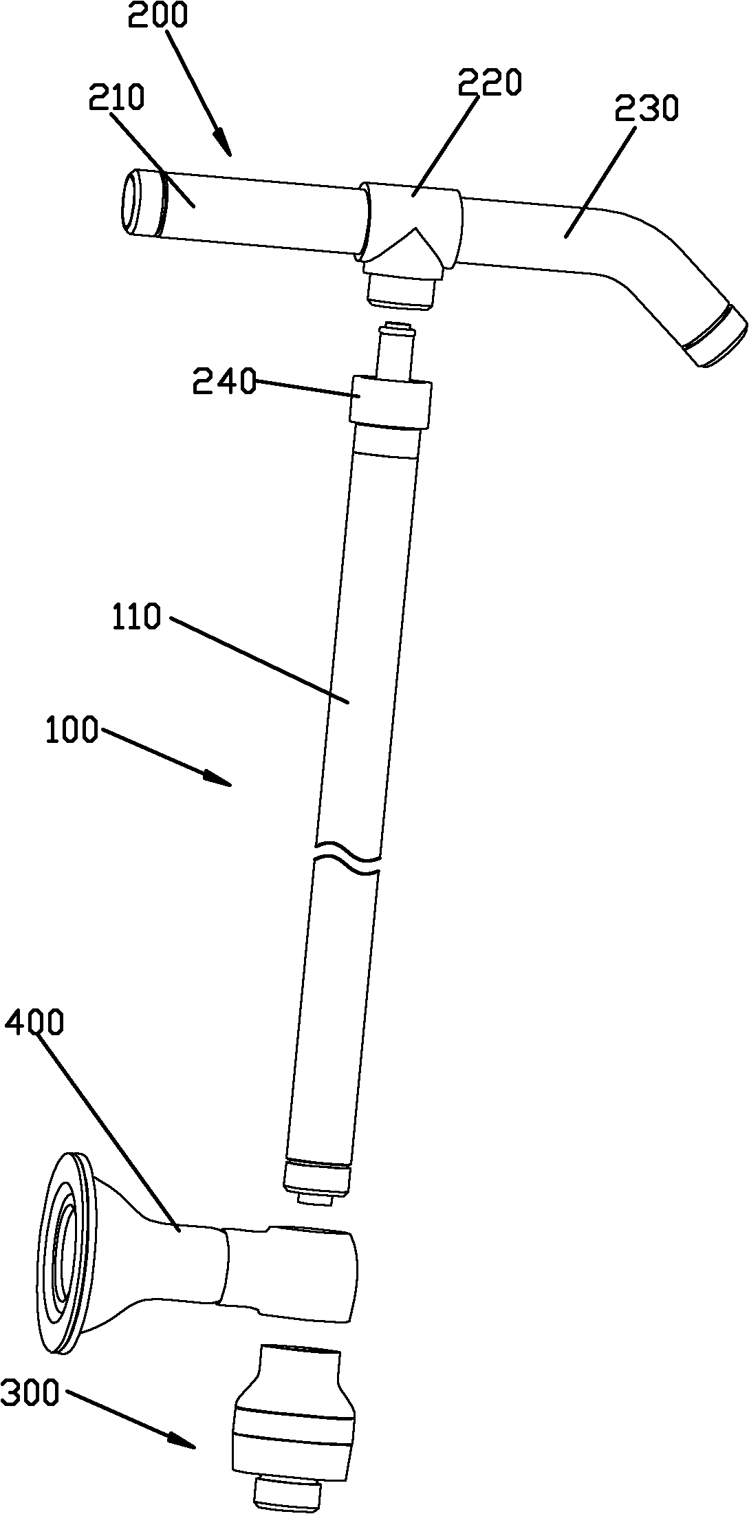
[0073] Please check Figure 1 to Figure 13 , the bottom rotation switching mechanism, which includes a tube assembly 100 , an arm assembly 200 , a switching device 300 and a suction cup assembly 400 .

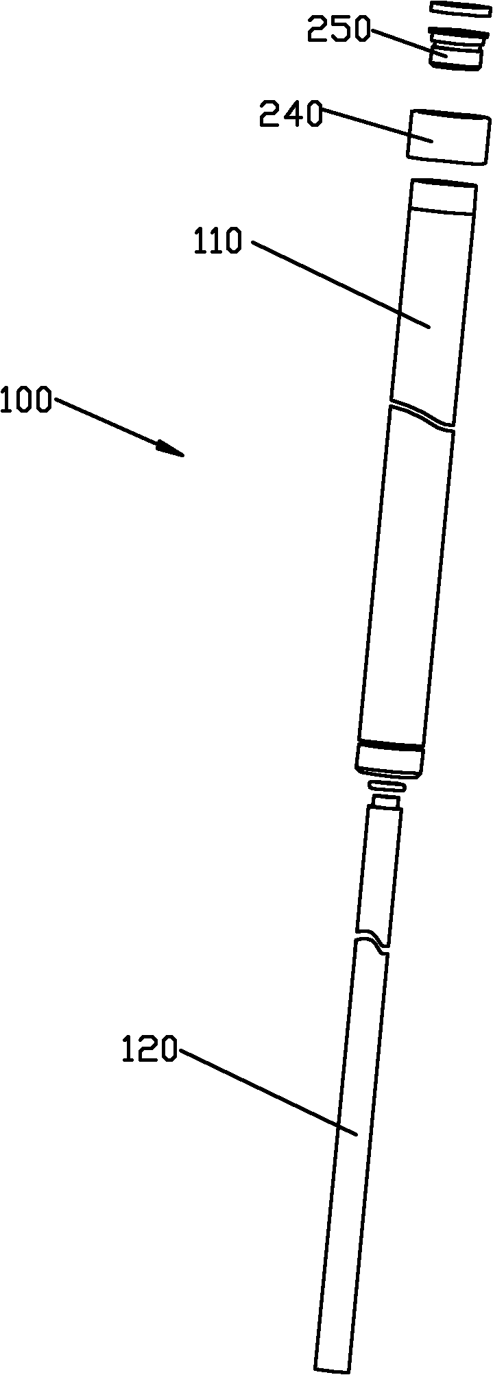
[0074] Please check Figure 1 to Figure 4 , the tube assembly 100, which includes an outer tube 110 and an inner tube 120 that are nested in each other, a water inlet channel 130 is formed between the outer tube 110 and the inner tube 120, and a first water channel 140 is formed between the inner tubes 120 .

[0075] Please check Figure 1 to Figure 4 , the arm assembly 200, which includes a rear pipe 210 connected to a water source, a fixed head 220 and a front pipe 230. The fixed head 220 is fixedly connected to the front pipe 230, the rear pipe 210, the outer pipe 110 and the inner pipe 120, and makes the rear pipe 210 connected to the water inlet channel 130 between the outer pipe 110 and the inner pipe 120, so that the The front pipe 230 is connected to the first water...


PUM


Abstract

The invention discloses a bottom rotary switching mechanism, comprising a tubular assembly and a switching device, wherein the tubular assembly comprises an outer tube and an inner tube which are mutually sleeved; a water inlet channel is formed between the outer tube and the inner tube; a first water path is formed in the inner tube; the switching device comprises a fixed unit, a sealing unit and a rotating sleeve; the fixed unit is fixedly connected with the outer tube and the inner tube and is provided with an adapting cavity and a second water path which are communicated with the water inlet channel; and the first water path and the second water path are respectively provided with an inlet. The sealing unit is movably connected in the adapting cavity. The switching of the first water path and the second water path can be realized by the movement of the sealing unit. The rotating sleeve is rotatably connected outside the fixed unit and connected the sealing unit in a driving way; and the sealing unit moves by rotating the rotating sleeve.

Description

technical field [0001] The invention relates to a bottom rotation switching mechanism. Background technique [0002] At present, most of the switching mechanisms combined with the support arm on the market use a two-way valve as a waterway switching component installed at the fixed head, and the waterway switching is performed by operating the switching component. However, in actual use, due to the high position of the switching component and the The switching principle of the switching component is also relatively complicated, which makes the operation inconvenient for the user. Contents of the invention [0003] The present invention provides a bottom rotation switching mechanism, which overcomes the disadvantage of inconvenient switching existing in the switching mechanism in the background technology. [0004] The adopted technical scheme that the present invention solves its technical problem is: [0005] Bottom rotary switching mechanism, which includes: [0006] ...

Claims


Application Information

Patent Timeline
Patent Type & Authority Applications(China)
IPC IPC(8): F16K11/08F16K11/00F16L3/12
Inventor 彭华胜李仁忠陈斌周华松彭海松
Owner XIAMEN SOLEX HIGH TECH IND CO LTD
Why Eureka
Eureka Blog
Learn More