
Drawer sliding rail

A drawer and slide rail technology, applied in drawers, furniture parts, household appliances, etc., can solve the problems of inconvenient access, loud noise, easy shaking, etc., and achieve the effect of unaffected stability and multi-functional expansion of space.

Inactive Publication Date: 2010-10-06
董旭晖
View PDF6 Cites 6 Cited by
  • Summary
  • Abstract
  • Description
  • Claims
  • Application Information

AI Technical Summary

Problems solved by technology

The double-track drawer slide rail includes a rail groove fixed on the cabinet body and a rail core installed on the drawer. The structure of this slide rail cannot completely pull out the drawer, and it is inconvenient to take and place items; The fixed rail and the moving rail installed in the drawer, the middle rail set between the fixed rail and the moving rail, also called the rail core, the cross section of the middle rail is 匚-shaped or I-shaped, and the 匚-shaped is a half-I-shaped
The force of the middle rail of the U-shaped cross-section is located in the center of the middle rail and the support plate is biased to one side, so it is easy to deform under long-term stress, resulting in poor stability and high noise
The support effect of the middle rail of the I-shaped section is better than that of the U-shaped one, but there is no lateral support force. The drawer is unstable and easy to shake during the drawer pushing and pulling process, which produces relatively large noise and affects the use effect and product life.
The middle rail of the I-shaped cross-section divides the empty space in the middle into two halves, which is not conducive to the utilization of space. The use of these spaces for functions such as remote control and automatic retraction of the extended slide rail will be limited by insufficient space
It is not advisable to increase the height of the intermediate connecting plate in order to increase the space, because the support stability of the slide rail is worse and the shaking is more severe after increasing its height

Method used


Image

  • Drawer sliding rail
  • Drawer sliding rail
  • Drawer sliding rail

Examples


Embodiment Construction

[0025] Embodiments of the present invention will be specifically described below in conjunction with the accompanying drawings.

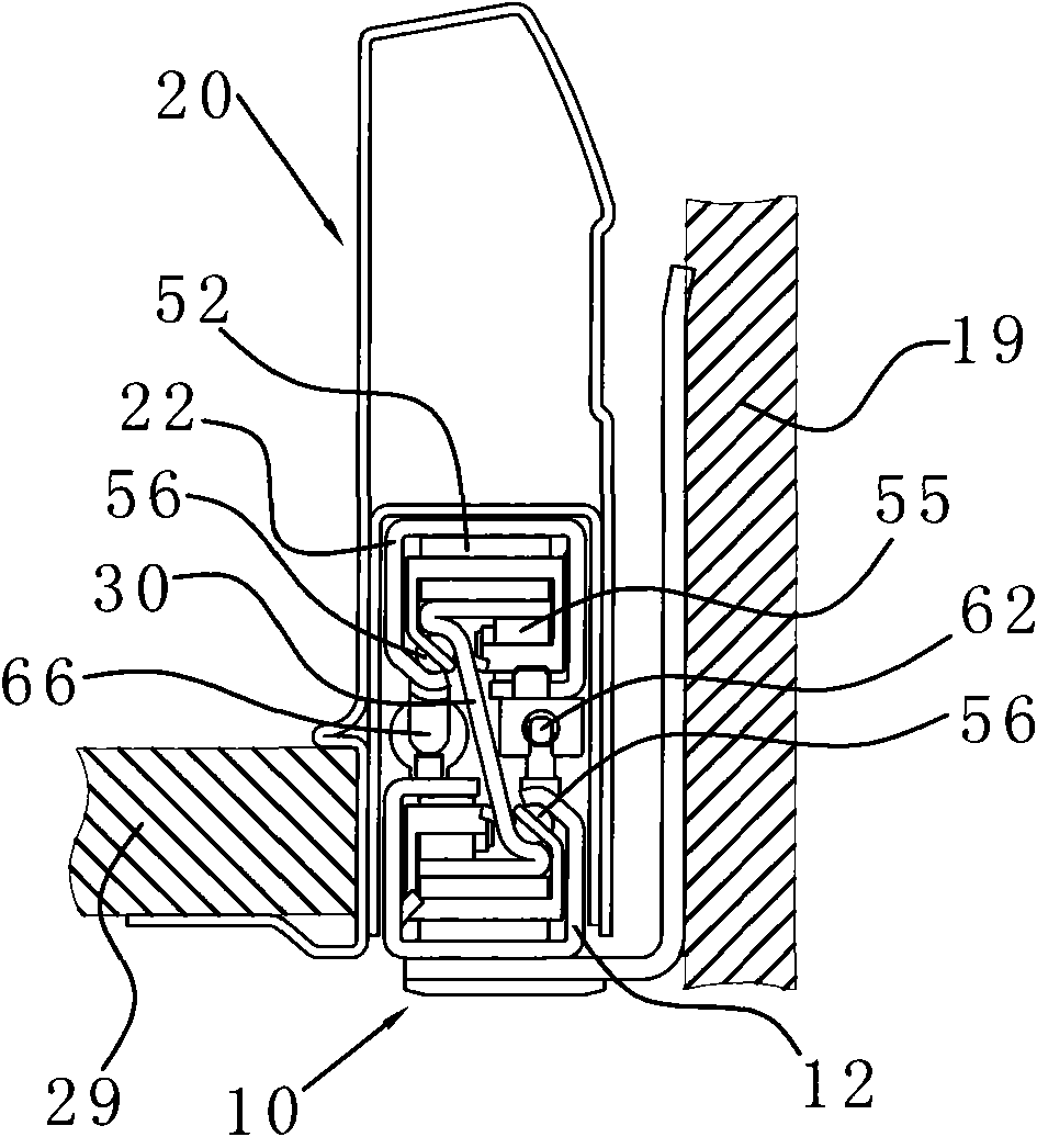
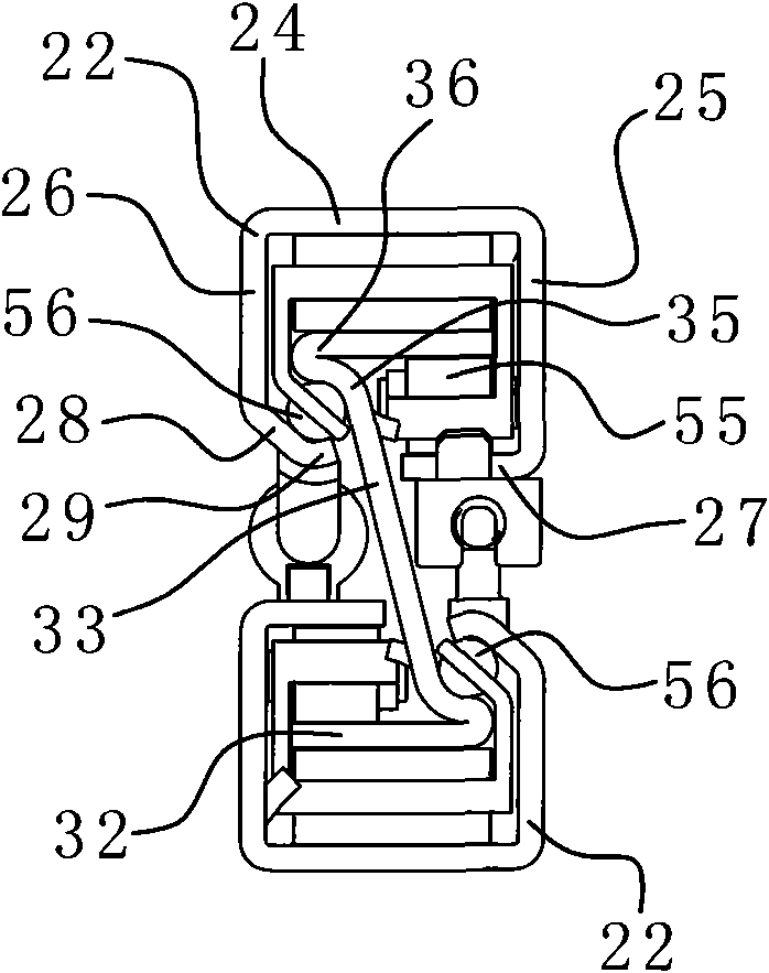
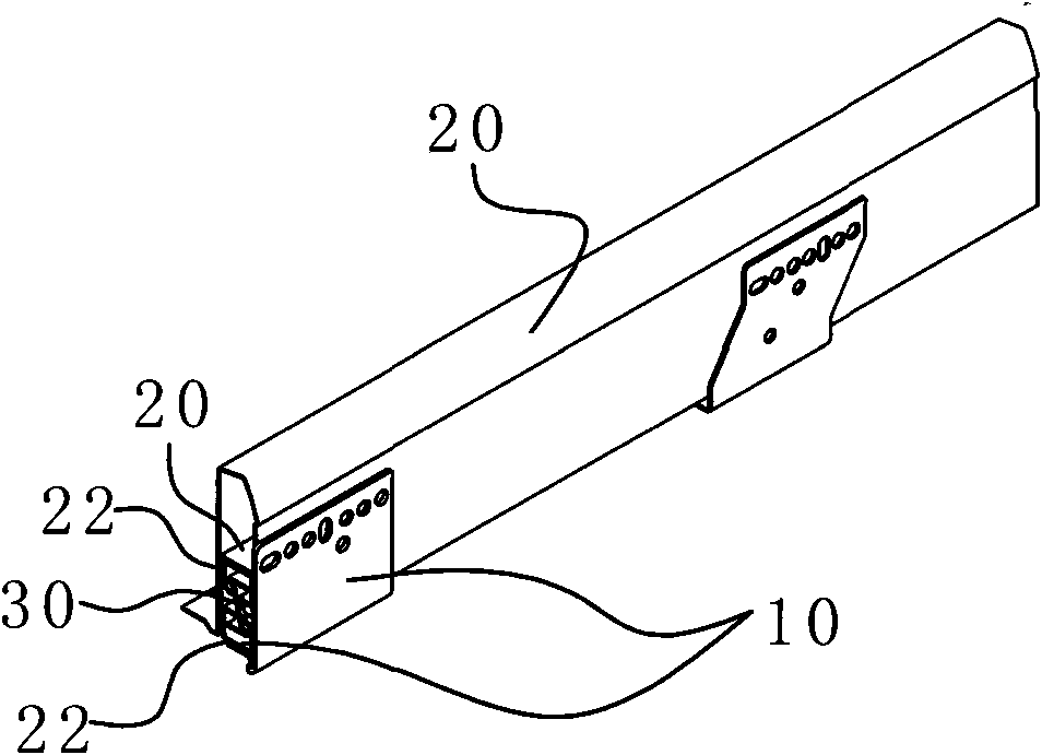
[0026] refer to figure 1 , figure 2 , image 3 , a drawer slide rail for installing a drawer in a drawer cabinet according to the present invention, which includes a fixed rail 10 fixed to the drawer cabinet body, a moving rail 20 fixed to the drawer, and a fixed rail 10 arranged between the moving rail 10 and the fixed rail. The middle rail 30 between the rails 20.

[0027] The above-mentioned middle rail 30 includes two horizontal plates 32 and an inclined plate 33 connecting the two horizontal plates, forming a Z-shaped cross section. Both the moving rail 20 and the fixed rail 10 have a rail sleeve 22 slidably sleeved on the horizontal plate 32 . Wherein the two horizontal plates 32 can be parallel to each other, more preferably, the horizontal plates are arranged horizontally, so that the installation of the slide rails is simpler and more ...


PUM


Abstract

The invention discloses a drawer sliding rail for mounting a drawer in a drawer cabinet and supporting the drawer, comprising a fixed rail fixed on the drawer cabinet, a movable rail fixed on the drawer and a middle rail arranged between the movable rail and the fixed rail. The middle rail comprises two transverse plates and an incline plate connecting the two transverse plates, and the middle rail has a Z-shaped cross section; and the movable rail and the fixed rail are both provided with rail sleeves capable of sleeving the transverse plates in a sliding mode. The incline plate obliquely divides the area between the two rail sleeves into two effective using spaces with triangular or trapezoid cross section, thus larger expanding device can be installed, and the incline plate can be heightened without influencing the stability, and larger functional expanding space can be provided. Two incline plates with opposite incline direction at the middle rails of both sides of the drawer forms a triangle mechanical structure having the best stability with the drawer, and a transverse supporting force is further provided, such that the drawer is very stable and shakes a little in the drawing process, and the noise is efficiently reduced.

Description

technical field [0001] The invention relates to a drawer, in particular to a drawer slide rail for installing the drawer in a drawer cabinet and supporting the drawer. Background technique [0002] At present, the commonly used drawer slides are double-track and three-track. The double-track drawer slide rail includes a rail groove fixed on the cabinet body and a rail core installed on the drawer. The structure of this slide rail cannot completely pull out the drawer, and it is inconvenient to take and place items; The fixed rail and the moving rail installed in the drawer, the middle rail set between the fixed rail and the moving rail, also called the rail core, the cross section of the middle rail is U-shaped or I-shaped, and the U-shaped is half I-shaped. The force of the middle rail of the U-shaped section is located in the center of the middle rail and the support plate is biased to one side, so it is easy to deform under long-term stress, resulting in poor stability a...

Claims


Application Information

Patent Timeline
IPC IPC(8): A47B88/04A47B88/14
Inventor 董旭晖
Owner 董旭晖
Learn More