
Semiconductor process equipment and O-shaped ring thereof

A process equipment and semiconductor technology, applied in semiconductor/solid-state device manufacturing, electrical components, circuits, etc., can solve problems such as loss of sealing effect, uncertain effective time of viscose 4, and influence on overall process yield, so as to prevent fluid leakage , good sealing effect

Inactive Publication Date: 2010-09-22
TAIWAN SEMICON MFG CO LTD +1
View PDF5 Cites 8 Cited by
  • Summary
  • Abstract
  • Description
  • Claims
  • Application Information

AI Technical Summary

Problems solved by technology

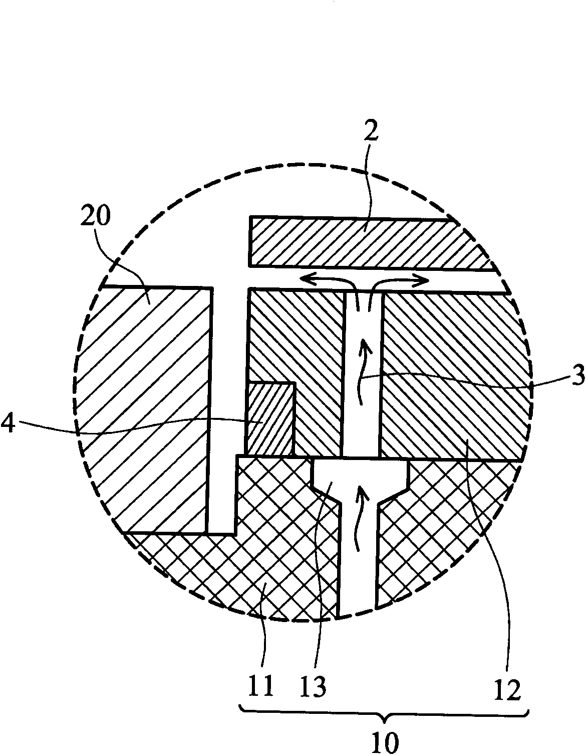
However, referring to Figure 1d , as the viscose 4 will be etched by the plasma particles and wear away, it will lose its sealing effect after long-term use
I

Method used


Image

  • Semiconductor process equipment and O-shaped ring thereof
  • Semiconductor process equipment and O-shaped ring thereof
  • Semiconductor process equipment and O-shaped ring thereof

Examples


Embodiment Construction

[0052] refer to Figure 2a , Figure 2b , which shows a semiconductor process equipment (plasma etching equipment) 100 according to the first embodiment of the present invention, which is used to perform a process on a wafer 2 . Figure 2b for Figure 2a Enlarged view of part A1 in. The semiconductor process equipment 100 includes a wafer base 10 , an extended covering element 20 , an O-ring (O-ring body) 110 and a cavity 30 . The crystal seat 10 is disposed in the cavity 30 . The crystal seat 10 includes a crystal seat body 11, a fluid supply unit 13 and a carrier element 12, the carrier element 12 is arranged on the crystal seat body 11, the wafer 2 is placed on the carrier element 12, the fluid supply The unit 13 is disposed in the base body 11 and provides a fluid 3 to the wafer 2 through the carrier element 12 . A groove 14 is formed on a side surface 15 of the crystal base 10 where the base body 11 and the carrier element 12 are connected. The extending covering el...


PUM


Abstract

The invention relates to semiconductor process equipment and an O-shaped ring thereof. The equipment is used for implementing process on a wafer and comprises a wafer seat and an O-shaped ring, wherein the wafer seat comprises a wafer seat main body, a fluid supplying unit and a bearing element. The bearing element is arranged on the bearing element. The fluid supplying unit is arranged in the wafer seat main body and provides fluid to the wafer. A channel is formed on the connecting part of the wafer seat main body and the bearing element, which is arranged on the wafer seat side of the wafer seat. The O-shaped ring is arranged in the channel. By arranging ribs, the radial strength of the O-shaped ring can be intensified, and the O-shaped ring is prevented from generating flexure in radial direction. In addition, by properly setting the ratio of the radial thickness of the main body to the radial thickness of the rib, the invention can simultaneously provide sufficient flexure-prevention and sealing effects. The rib is helpful to identify the outside surface, thereby avoiding false assembly.

Description

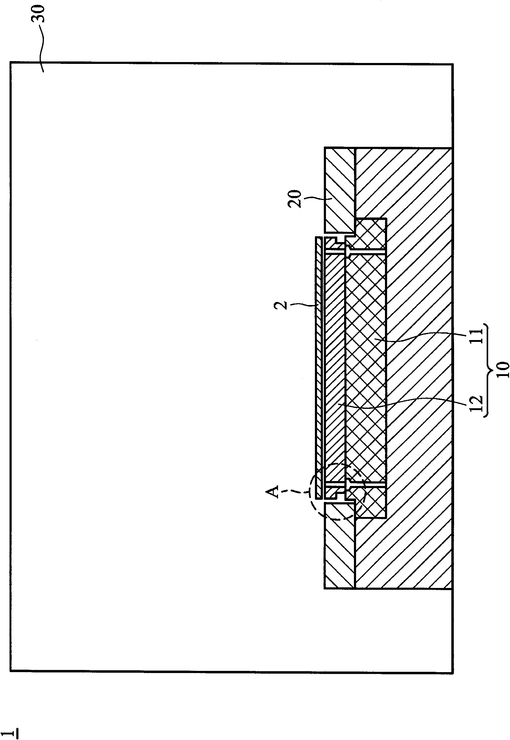
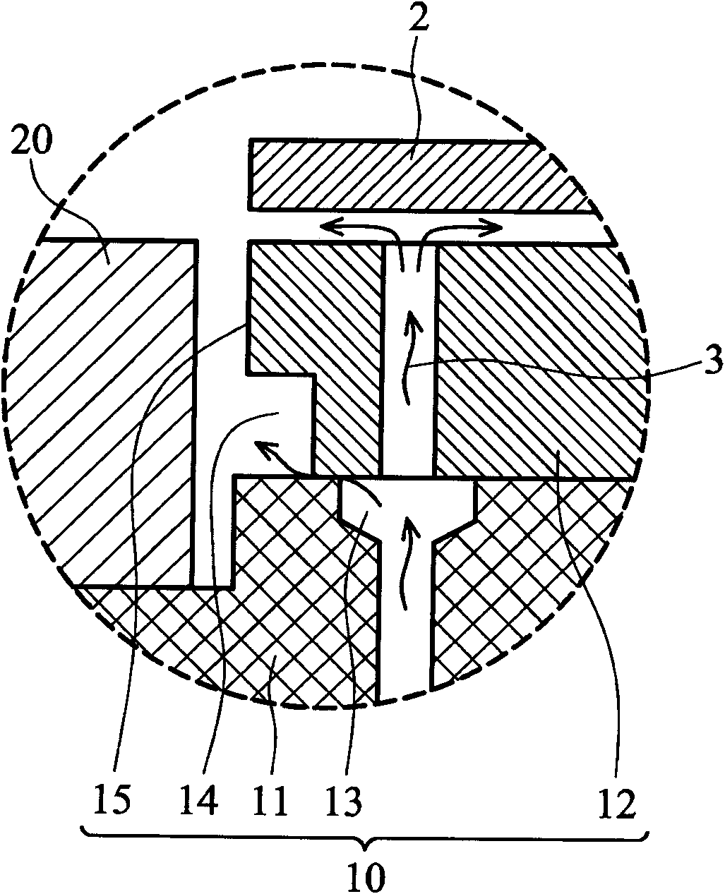
technical field [0001] The invention relates to an O-ring, in particular to an O-ring applied to semiconductor process equipment. Background technique [0002] refer to Figure 1a , Figure 1b , which shows a known semiconductor process equipment (plasma etching equipment) 1 for performing a process on a wafer 2 . Figure 1b for Figure 1a Enlarged view of part A in . The semiconductor process equipment 1 includes a wafer base 10 , an extended covering element 20 and a cavity 30 . The crystal seat 10 is disposed in the cavity 30 . The crystal seat 10 includes a crystal seat body 11, a fluid supply unit 13 and a carrier element 12, the carrier element 12 is arranged on the crystal seat body 11, the wafer 2 is placed on the carrier element 12, the fluid supply The unit 13 is arranged in the base body 11, and provides a fluid 3 to the wafer 2 through the carrier element 12, wherein a groove 14 is formed on the base side 15 of the base 10. The connection between the body 11...

Claims


Application Information

Patent Timeline
IPC IPC(8): H01L21/00H01L21/683
Inventor 张祐语刘旭水黄俊尧白峻荣
Owner TAIWAN SEMICON MFG CO LTD
Learn More