Radial clamping system for a timepiece component

A clock and component technology, applied in the system field, can solve problems such as the inability to apply brittle materials

Active Publication Date: 2010-09-22
NIVAROX FAR
View PDF5 Cites 4 Cited by
  • Summary
  • Abstract
  • Description
  • Claims
  • Application Information

AI Technical Summary

Problems solved by technology

However, this construction cannot be applied to brittle materials where plastically deformed regions do not actually exist

Method used


Image

  • Radial clamping system for a timepiece component
  • Radial clamping system for a timepiece component
  • Radial clamping system for a timepiece component

Examples


Embodiment Construction

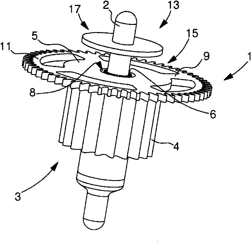
[0019] like Figure 1-4 As shown, the invention relates to a timepiece component, generally indicated by the reference numeral 1 , cooperating with a support element 3 . In the example used below, timepiece component 1 is a substantially disc-shaped wheel set and support element 3 is a cylindrical arbor with circular cross section. However, they are not limited to these forms.

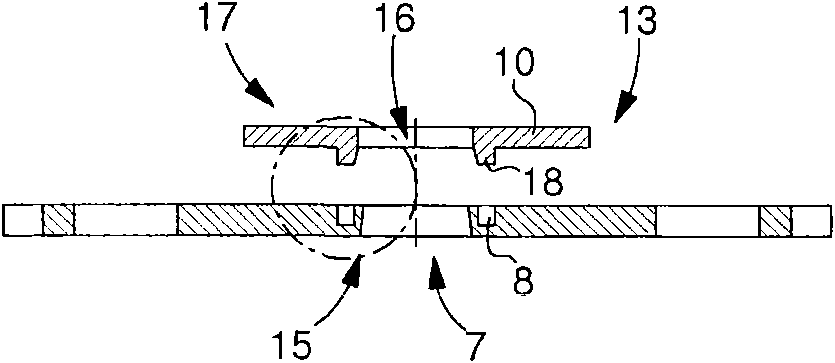
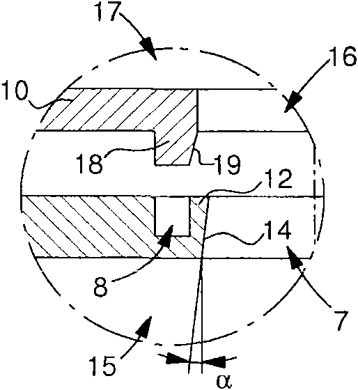
[0020] figure 1 The example shown in shows a timepiece component 1 mounted on a support element 3 . The support element 3 preferably comprises an arbor 2 integral with a pinion 4 . The timepiece component 1 has a hub 5 with an opening 7 , four arms 9 and a toothed rim 11 . Advantageously, according to the invention, the timepiece component 1 is mounted on the support element 3 by means of a clamping system 13 arranged around the opening 7 passing through said component.

[0021] Clamping system 13 serves to exert a radial force on arbor 2 in order to secure timepiece component 1 to support element...


PUM


Abstract

The invention relates to a timepiece component (1) that has an aperture (7) for receiving a support element (3) and includes a clamping system (13) for exerting radial force, allowing said timepiece component to be secured to said support element. According to the invention, the clamping system (13) includes a radial clamping device (15) that has a crown (6) for exerting said radial force and a concentric, blind recess (8) spaced apart from said aperture, for allowing said crown to travel. The invention concerns the field of timepieces.

Description

technical field [0001] The invention relates to a radial clamping system for a timepiece component, in particular such a system for securing said component to a support element, such as a pivoting arbor. Background technique [0002] It is known to fix a timepiece wheel set by pushing its central through hole on a pivoting arbor between the bridge and the main plate. This configuration is very widely used for metallic materials. However, this configuration cannot be applied to brittle materials where plastically deformed regions do not actually exist. Contents of the invention [0003] An object of the present invention is to overcome all or part of the aforementioned drawbacks by proposing a timepiece component whose radial clamping system notably utilizes elastically deformable areas of material to secure itself to its support element. [0004] The invention therefore relates to a timepiece component having an aperture for receiving a support element and a clamping sys...

Claims


Application Information

Patent Timeline
Patent Type & Authority Applications(China)
IPC IPC(8): G04B13/02G04B33/00
CPCG04B13/02G04B13/021
Inventor M·韦拉尔多T·科尼斯J-P·蒂埃博J-B·彼德斯P·卡森
Owner NIVAROX FAR
Why Eureka
Try Eureka