
Image forming apparatus

An image and image reading technology, which is applied in stack receiving devices, electric recording technology using charge patterns, and equipment for electric recording technology using charge patterns, etc. It can solve problems such as wrong actions, contacting operation panels, and cost increases , to achieve the effect of preventing wrong operation, simple structure and ensuring interval

Inactive Publication Date: 2010-09-15
KYOCERA DOCUMENT SOLUTIONS INC
View PDF5 Cites 5 Cited by
  • Summary
  • Abstract
  • Description
  • Claims
  • Application Information

AI Technical Summary

Problems solved by technology

[0007] As described above, if the output tray is arranged at the same height as the operation panel or at a lower position than the operation panel, there is a possibility that the hand holding the paper will touch the operation panel when the paper is taken out from the output tray. wrong action problem
[0008] In addition, in order to prevent the erroneous operation when taking out the paper, the following image forming apparatus is known, which prevents the erroneous operation when taking out the paper from the paper discharge tray by providing a detection unit and a control unit, wherein the detection unit detects the error from the paper discharge. The control unit disables at least a part of the operations on the operation panel when the detecting unit detects the removal of the paper after the image formation is completed on the tray.
[0009] However, since this image forming apparatus needs a detection unit for detecting that the hand has been inserted into the body, the cost increases accordingly. In addition, depending on the arrangement state of the detection unit, it may not be possible to reliably detect that the hand has been inserted into the body. It may not be possible to prevent erroneous actions when removing paper from the output tray

Method used


Image

  • Image forming apparatus
  • Image forming apparatus
  • Image forming apparatus

Examples


Embodiment Construction

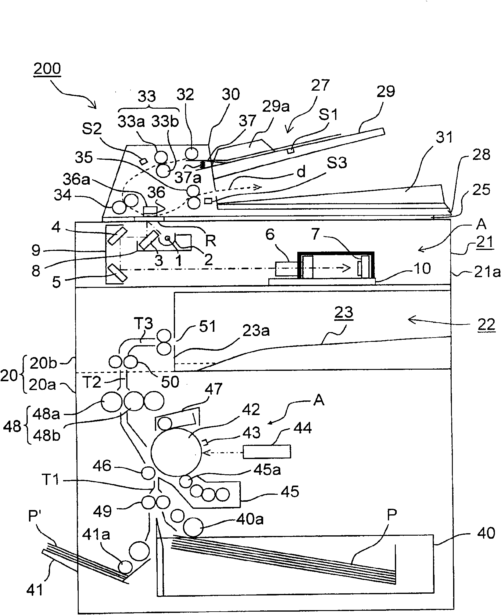
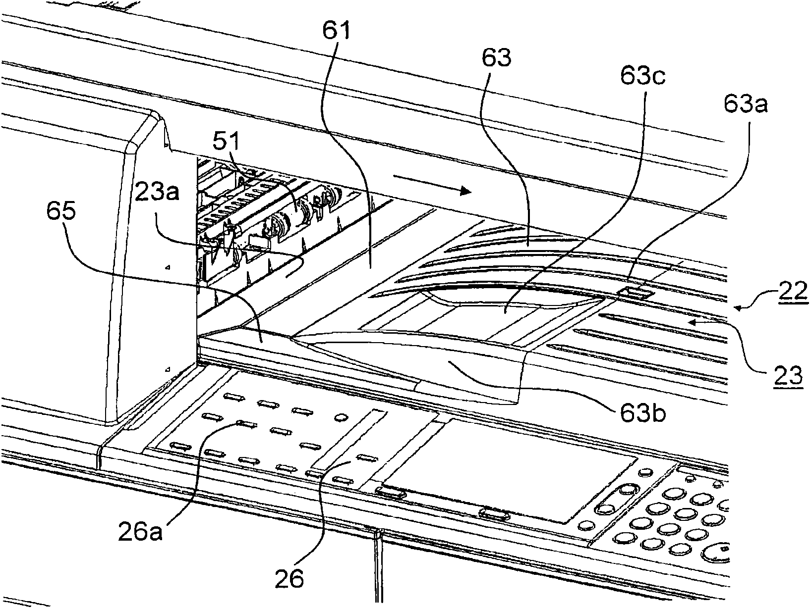
[0023] Hereinafter, embodiments of the present invention will be described with reference to the drawings. figure 1 is an external perspective view of an image forming apparatus according to an embodiment of the present invention, figure 2 It is a schematic cross-sectional view showing the internal structure of the image forming apparatus according to this embodiment.

[0024] Such as figure 1 with figure 2 As shown, the image forming apparatus 200 is a digital copying machine of a so-called internal discharge type, and includes a main body casing 20 and an upper casing 21 disposed on the top thereof. The upper case 21 is provided with various mechanisms for reading the image of the document as an electrical signal, which will be described later. Various mechanisms described later that transfer images to paper.

[0025] In this embodiment, the main body case 20 includes a lower case 20a, and a connection case 20b extending above it along the left side and connected to ...


PUM


Abstract

The present invention relates to an image forming apparatus utilizing internal paper ejection. A paper ejection tray disposed on the bottom of a paper ejection space in the apparatus includes a flat portion extending substantially horizontally by a predetermined distance downstream from a wall on the upstream side in a paper ejection direction; a sloping portion sloping upward downstream from theflat portion; and a protruding portion sloping upward from the flat portion to the front of the apparatus, the top of the protruding portion being higher than an operation panel. According to the image forming apparatus with said structure, it is possible to prevent a misoperation due to contact to the operation panel for fetching papers.

Description

technical field [0001] The present invention relates to image forming apparatuses such as copiers, printers, and facsimile machines, and more particularly, to an image forming apparatus capable of preventing troubles that occur when paper is taken out from a paper discharge tray disposed in a paper discharge space in a machine body. Background technique [0002] Conventionally, in an image forming apparatus such as a copying machine using an electrophotographic method, there is an in-body discharge system that has an image reading section above the image forming section and an in-body paper discharge space between the image forming section and the image reading section. A paper-type image forming device. A paper discharge tray is disposed at the bottom of the paper discharge space in the body, and an operation panel is disposed adjacent to the front side of the device main body of the paper discharge tray. Paper discharged to the paper discharge tray after image formation i...

Claims


Application Information

Patent Timeline
Patent Type & Authority Applications(China)
IPC IPC(8): G03G15/00B65H29/00
CPCB65H2601/325G03G15/6552B65H31/02G03G2215/00421B65H2405/1114B65H2801/06B65H2405/1111
Inventor 中山彻
Owner KYOCERA DOCUMENT SOLUTIONS INC
Learn More