Water-receiving bucket of dehumidifier

A technology for dehumidifiers and buckets, applied in the direction of preventing condensed water, etc., can solve problems such as bucket handles are easy to break, and achieve the effects of improving reliability, strengthening stress-bearing parts, and reducing adverse effects

Inactive Publication Date: 2010-08-25
LG ELECTRONICS (TIANJIN) APPLIANCES CO LTD
View PDF0 Cites 1 Cited by
  • Summary
  • Abstract
  • Description
  • Claims
  • Application Information

AI Technical Summary

Problems solved by technology

The water-receiving bucket of this structure is only subjected to force by the contact of the strip-shaped protruding strip 24 and the barrel body 21. When the water-receiving bucket 20 is filled with water, the weight of the water is about 10Kg. At this time, the two sides of the water-receiving bucket are facing outwards. Due to the small contact area of ​​the bar, the handle of the bucket is easy to break due to the force

Method used


Image

  • Water-receiving bucket of dehumidifier
  • Water-receiving bucket of dehumidifier
  • Water-receiving bucket of dehumidifier

Examples


Embodiment Construction

[0022] Below in conjunction with accompanying drawing and specific embodiment the present invention is described in further detail:

[0023] The working principle of the dehumidifier of the present invention is the same as that of the prior art, and the prior art can be referred to, so it will not be described again. The difference between the present invention and the prior art is that the structure of the water receiving bucket of the dehumidifier is different, and a detailed description is given below:

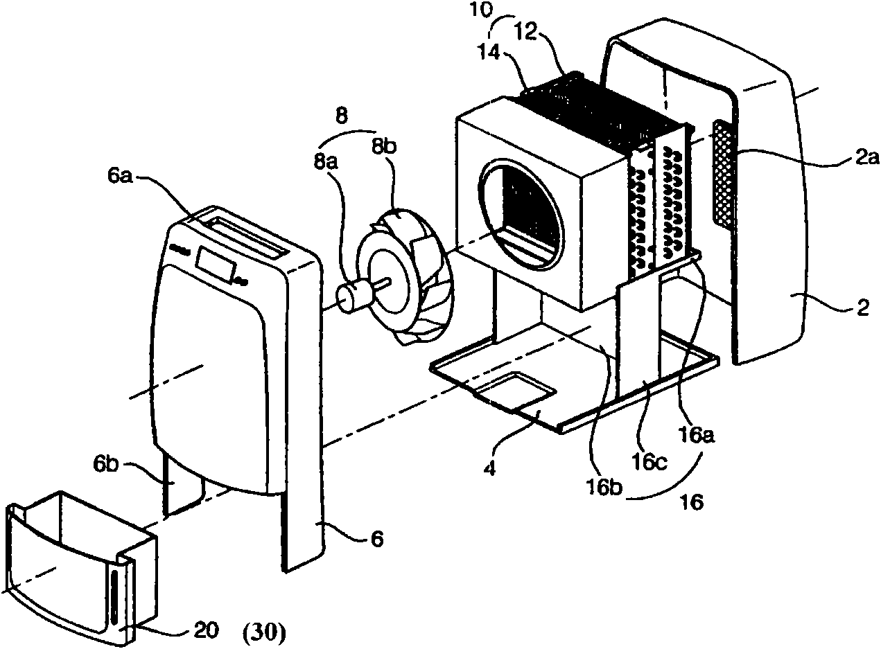
[0024] Such as figure 1 As shown, the dehumidifier of the present invention includes: a housing body 2 , a chassis 4 , a front panel 6 , a blower 8 , a heat exchanger 10 , a compressor (not shown), a drain pan 16 , and a bucket 30 . Among them, the front and bottom of the casing main body 2 are open, and the suction port 2a is formed on the rear. The chassis 4 is combined with the bottom surface of the housing body 2 . The front panel 6 is combined with the front of the c...


PUM


Abstract

The invention discloses a water-receiving bucket of a dehumidifier, comprising a bucket body and a bucket handle. Pear-shaped installing holes used for installing the bucket handle are respectively formed on the upper parts of two side surfaces of the bucket body; large circular holes of the pear-shaped installing holes are positioned in an oblique lower side, and small circular holes are positioned in an oblique upper side; a first cylindrical lug boss and a second cylindrical lug boss are sequentially formed at the internal sides of both ends of the elongated C-shaped bucket handle from inside to outside; the diameter of the second cylindrical lug boss is larger than that of the first cylindrical lug boss; the second cylindrical lug boss is slightly smaller than the large circular holes and can just pass through the large circular holes; and the diameter of the first cylindrical lug boss is designed to meet that the first cylindrical lug boss can just slide into the small circular holes from the pear-shaped large circular holes under the extrusion condition. The invention strengthens stresses positions of the bucket handle, changes the linear contact into the overall circumferential contact, reduces the defect rate and improves the product reliability.

Description

technical field [0001] The invention relates to a dehumidifier, in particular to a dehumidifier bucket. Background technique [0002] Generally, a dehumidifier is a device that sucks indoor humid air into the shell of the dehumidifier, and after reducing the humidity through a heat exchanger, discharges the air with reduced humidity to the room to reduce the indoor humidity. The above-mentioned heat exchanger is composed of a condenser and an evaporator with a refrigerant inside. [0003] Such as figure 1 As shown, the prior art dehumidifier includes: a housing body 2, a chassis 4, a front panel 6, a blower 8, a heat exchanger 10, a compressor (not shown), a drain pan 16, and a bucket 20. Among them, the front and bottom of the casing main body 2 are open, and the suction port 2a is formed on the rear. The chassis 4 is combined with the bottom surface of the housing body 2 . The front panel 6 is combined with the front of the casing main body 2, and has an exhaust port 6...

Claims


Application Information

Patent Timeline
IPC IPC(8): F24F13/22
Inventor 张可
Owner LG ELECTRONICS (TIANJIN) APPLIANCES CO LTD
Why Eureka
Try Eureka