
Method for producing a radiation-emitting component and radiation-emitting component

A technology for emitting radiation and devices, which is used in the field of manufacturing radiation-emitting devices and radiation-emitting devices, and can solve problems such as radiation intensity decline

Inactive Publication Date: 2013-04-10
OSRAM OPTO SEMICON GMBH & CO OHG
View PDF0 Cites 0 Cited by
  • Summary
  • Abstract
  • Description
  • Claims
  • Application Information

AI Technical Summary

Problems solved by technology

Hence, starting from the central axis of the radiation spectrum, the radiation intensity decreases relatively rapidly outward

Method used


Image

  • Method for producing a radiation-emitting component and radiation-emitting component
  • Method for producing a radiation-emitting component and radiation-emitting component
  • Method for producing a radiation-emitting component and radiation-emitting component

Examples


Embodiment Construction

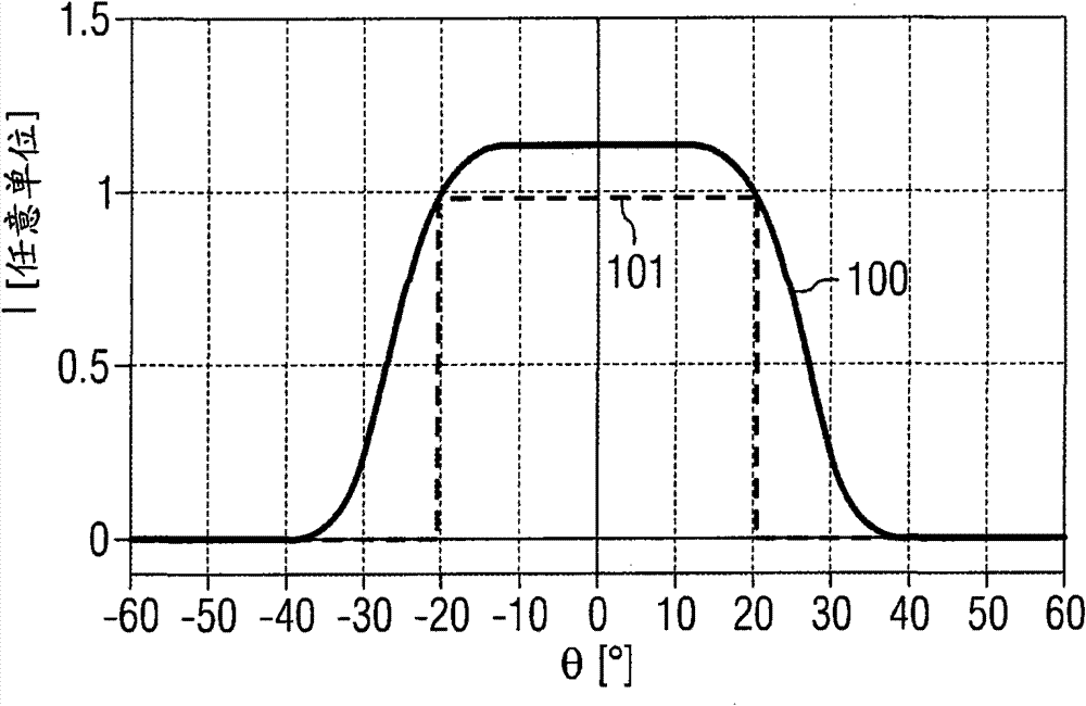
[0068] FIG. 1 shows the profile of the intensity I of the far-field profile predefined for the radiation-emitting component. Here, the intensity I is shown as a function of the angle Θ with the main radiation direction of the device. The intensity profile exhibits a plateau-shaped profile at an angle of approximately + / - 15°, in which the intensity is almost constant. In this case, the dashed line 101 forms the boundary of the rectangle with the largest area that lies below the intensity curve 100 . Here, the rectangle fills approximately 68.8% of the area constructed below the intensity profile 100 . In contrast to this, in image 3 A corresponding intensity profile 300 is shown in the case of a Gaussian radiation spectrum, wherein the intensity profile 300 has an associated rectangle 301 with the largest area. In this case, the rectangle 301 with the largest area occupies approximately 48.4% of the area enclosed by the intensity variation curve 300 . therefore, Figure ...


PUM


Abstract

A method of producing a radiation-emitting component is provided. A far field radiation pattern is predetermined. From the predetermined radiation pattern a refractive index profile for the radiation-emitting component is determined in a direction extending perpendicularly to a main emission direction of the component. A structure is determined for the component, such that the component includes the previously determined refractive index profile. The component is configured according to the previously determined structure.

Description

technical field [0001] The present application relates to a method for producing a radiation-emitting component and to a radiation-emitting component. Background technique [0002] In the case of semiconductor lasers used as pump lasers, it is desirable to emit laser radiation with a far field that is as homogeneous as possible. However, semiconductor lasers typically emit radiation with a Gaussian-like far field. Hence, starting from the central axis of the radiation spectrum, the radiation intensity decreases relatively rapidly outwards. SUMMARY OF THE INVENTION [0003] One object is to describe a method by which a solid-state laser can be produced whose far field is better suited for the application predetermined for the laser. The laser will in particular have an improved homogeneity of the emitted radiation in the far field. [0004] This task is solved by a method and a radiation-emitting device according to the description below. Advantageous extensions and imp...

Claims


Application Information

Patent Timeline
Patent Type & Authority Patents(China)
IPC IPC(8): H01S5/40H01S5/20H01S5/00H01S5/10H01S5/22
CPCH01S5/4043H01S5/22H01S2301/18H01S5/0035H01S2301/206H01S5/2004H01S5/3095H01S5/1064
Inventor P·布里克
Owner OSRAM OPTO SEMICON GMBH & CO OHG
Learn More