Closed type compressor and freezing apparatus using the same
A compressor and hermetic technology, applied in mechanical equipment, machines/engines, liquid displacement machinery, etc., can solve the problems of increased wear, early wear of piston 23, increased sliding loss, etc.
- Summary
- Abstract
- Description
- Claims
- Application Information
AI Technical Summary
Problems solved by technology
Method used
Image

Examples
example 1
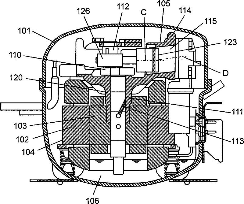
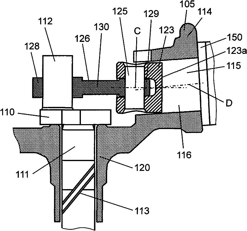
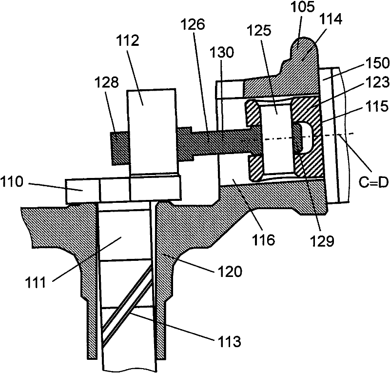
[0050] figure 1 It is a longitudinal sectional view of the hermetic compressor in the preferred embodiment 1 of the present invention. figure 2 is an enlarged sectional view of the main part when the compressive load is not acting in the same preferred embodiment. image 3 is an enlarged sectional view of a main part when a compressive load acts in the same preferred embodiment. Figure 4 It is a sectional view of main parts showing the relative positions of the bearing portion and the compression chamber in the same preferred embodiment. Figure 5 is a characteristic diagram showing the results of experiments based on the same preferred embodiment.
[0051] exist Figure 1 to Figure 3 Among them, a closed container 101 accommodates a motor drive element 104 having a stator 102 and a rotor 103 , and a compression element 105 driven by the motor drive element 104 . Lubricating oil 106 is contained at the bottom of the airtight container 101 .
[0052] The shaft 110 has a...
example 2
[0085] In preferred embodiment 1, the compression chamber 115 is formed by inclining the axis D of the compression chamber 115 corresponding to the inclination of the piston 123 . However, in the present preferred embodiment, in addition to the configuration of the preferred embodiment 1, a tapered portion for forming the compression chamber 115 is formed in the cylindrical hole portion 116 . Therefore, in this preferred embodiment, explanations about the same configuration as in preferred embodiment 1 are omitted, and configurations different from preferred embodiment 1 are mainly explained.
[0086] Figure 1 to Figure 4 Also applicable to this preferred embodiment. Figure 7 is a sectional view of the main part near the compression chamber in this preferred embodiment, showing a state where the piston is located at the bottom dead center. Figure 8 is a sectional view of main parts near the compression chamber in the same preferred embodiment, showing a state in which the...
example 3
[0127] In preferred embodiments 1 and 2, the compression chamber 115 is formed by inclining the axis of the compression chamber 115 corresponding to the inclination of the piston 123 . However, in the present preferred embodiment, the pin hole is formed by inclining the axis center of the pin hole corresponding to the inclination of the connecting rod which is caused to inclination by the inclination of the shaft 110 when the compression load of compressing refrigerant gas acts.
[0128] Figure 10 It is a vertical sectional view of the hermetic compressor in this preferred embodiment. Figure 11 is an enlarged sectional view of the main part when the compressive load is not acting in the same preferred embodiment. Figure 12 is an enlarged sectional view of a main part when a compressive load acts in the same preferred embodiment. Figure 13 is a cross-sectional view of main parts showing the relative positions of the piston and the pin hole in the same preferred embodiment...
PUM
 Abstract
Description
Claims
Application Information
 - R&D
- Intellectual Property
- Life Sciences
- Materials
- Tech Scout
- Unparalleled Data Quality
- Higher Quality Content
- 60% Fewer Hallucinations
Browse by: Latest US Patents, China's latest patents, Technical Efficacy Thesaurus, Application Domain, Technology Topic, Popular Technical Reports.
© 2025 PatSnap. All rights reserved.Legal|Privacy policy|Modern Slavery Act Transparency Statement|Sitemap|About US| Contact US: help@patsnap.com