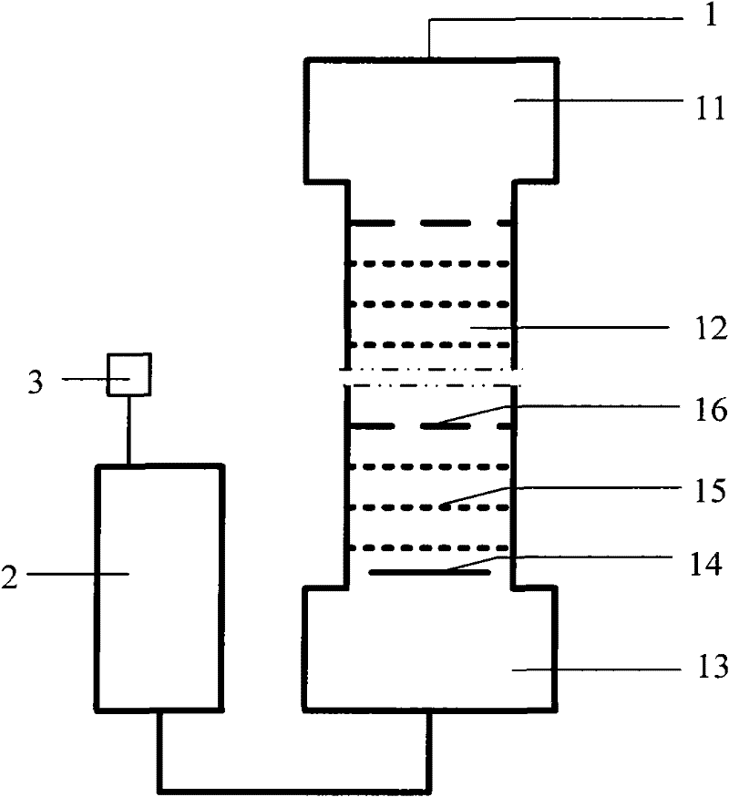
Extraction equipment of caprolactam
An extraction equipment and caprolactam technology, applied in the separation/purification of lactam, organic chemistry, chemical instruments and methods, etc.
- Summary
- Abstract
- Description
- Claims
- Application Information
AI Technical Summary
Problems solved by technology
Method used
Image
Examples
Embodiment 1
[0020] A kind of caprolactam extraction equipment, the schematic diagram is as figure 1 As shown, the equipment includes two parts, a tower body 1 and a buffer 2; the tower body 1 is divided into three parts: a tower top expansion section 11, a tower body 12 and a tower bottom expansion section 13, and above the tower body 12 is a tower top expansion section Section 11, under the tower body 12 is the tower bottom expansion section 13, the cross-sectional area of the tower top expansion section 11 and the tower bottom expansion section 13 are all greater than the cross-sectional area of the tower body 12, the buffer 2 and the tower bottom expansion section 13 is connected at the bottom, and an oil phase distributor 14 is installed at the bottom of the tower body 12, and hydrophilic sieve plates 15 and hydrophobic deflectors 16 are alternately placed on the oil phase distributor 14 in the tower body 12 from bottom to top, The placement method of hydrophilic sieve plates and...
Embodiment 2
[0022] A kind of caprolactam extraction equipment, the schematic diagram is as figure 1 As shown, the equipment includes two parts, a tower body 1 and a buffer 2; the tower body 1 is divided into three parts: a tower top expansion section 11, a tower body 12 and a tower bottom expansion section 13, and above the tower body 12 is a tower top expansion section Section 11, under the tower body 12 is the tower bottom expansion section 13, the cross-sectional area of the tower top expansion section 11 and the tower bottom expansion section 13 are all greater than the cross-sectional area of the tower body 12, the buffer 2 and the tower bottom expansion section 13 is connected at the bottom, and an oil phase distributor 14 is installed at the bottom of the tower body 12, and hydrophilic sieve plates 15 and hydrophobic deflectors 16 are alternately placed on the oil phase distributor 14 in the tower body 12 from bottom to top, The placement of the hydrophilic sieve plates and th...
Embodiment 3
[0024] A kind of caprolactam extraction equipment, the schematic diagram is as figure 1 As shown, the equipment includes two parts, a tower body 1 and a buffer 2; the tower body 1 is divided into three parts: a tower top expansion section 11, a tower body 12 and a tower bottom expansion section 13, and above the tower body 12 is a tower top expansion section Section 11, under the tower body 12 is the tower bottom expansion section 13, the cross-sectional area of the tower top expansion section 11 and the tower bottom expansion section 13 are all greater than the cross-sectional area of the tower body 12, the buffer 2 and the tower bottom expansion section 13 is connected at the bottom, and an oil phase distributor 14 is installed at the bottom of the tower body 12, and hydrophilic sieve plates 15 and hydrophobic deflectors 16 are alternately placed on the oil phase distributor 14 in the tower body 12 from bottom to top, The placement of the hydrophilic sieve plate and the...
PUM
 Abstract
Description
Claims
Application Information
 - Generate Ideas
- Intellectual Property
- Life Sciences
- Materials
- Tech Scout
- Unparalleled Data Quality
- Higher Quality Content
- 60% Fewer Hallucinations
Browse by: Latest US Patents, China's latest patents, Technical Efficacy Thesaurus, Application Domain, Technology Topic, Popular Technical Reports.
© 2025 PatSnap. All rights reserved.Legal|Privacy policy|Modern Slavery Act Transparency Statement|Sitemap|About US| Contact US: help@patsnap.com


