
Electrode device

An electrode device and electrode technology, which is applied in the direction of electric furnace heating, furnace, lighting and heating equipment, etc., can solve the problems that the electrode cannot be moved by the lifting device, cannot meet the requirements, and the conductive device moves, etc., and achieve stable lifting, reduced interference, and reliable power supply Effect

Active Publication Date: 2010-07-07
CHINA ENFI ENGINEERING CORPORATION
View PDF0 Cites 7 Cited by
  • Summary
  • Abstract
  • Description
  • Claims
  • Application Information

AI Technical Summary

Problems solved by technology

With the use of the electrode, the lower end of the electrode inserted into the furnace body will be continuously consumed, and the length inserted into the furnace body will become shorter. At this time, only relying on the lifting device to lift the electrode cannot meet the requirements, and the electrode needs to be lowered relative to the lifting device as a whole to compensate for the consumption of the electrode.
[0004] The lifting device and conductive device of the traditional electrode are fixed relative to the electrode. The electrode cannot move relative to the lifting device, and the conductive device cannot move relative to the electrode. Therefore, the maximum electrode length that can be inserted into the furnace body of the electric furnace is fixed. When the electrode is used When a certain amount is consumed, the requirement cannot be met
For this reason, it is necessary to cut off the power, disconnect the connection between the electrode and the power supply device at the same time, re-adjust the relative position of the electrode and the power supply device, and then fix the power supply device again, clamp the electrode with the power supply device, that is, compensate the electrode by manually pressing and releasing. Therefore, the operation is complicated, the cost is high, the furnace needs to be shut down, the efficiency is reduced, and it is also dangerous

Method used


Image

  • Electrode device
  • Electrode device
  • Electrode device

Examples


Embodiment Construction

[0033] Embodiments of the present invention are described in detail below, examples of which are shown in the drawings, wherein the same or similar reference numerals designate the same or similar elements or elements having the same or similar functions throughout. The embodiments described below by referring to the figures are exemplary only for explaining the present invention, and should not be construed as limiting the present invention.

[0034] An electrode device according to an embodiment of the present invention is described below with reference to the accompanying drawings.

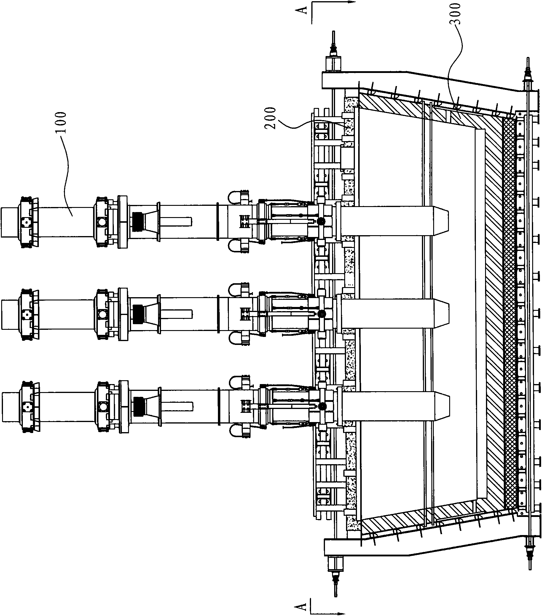
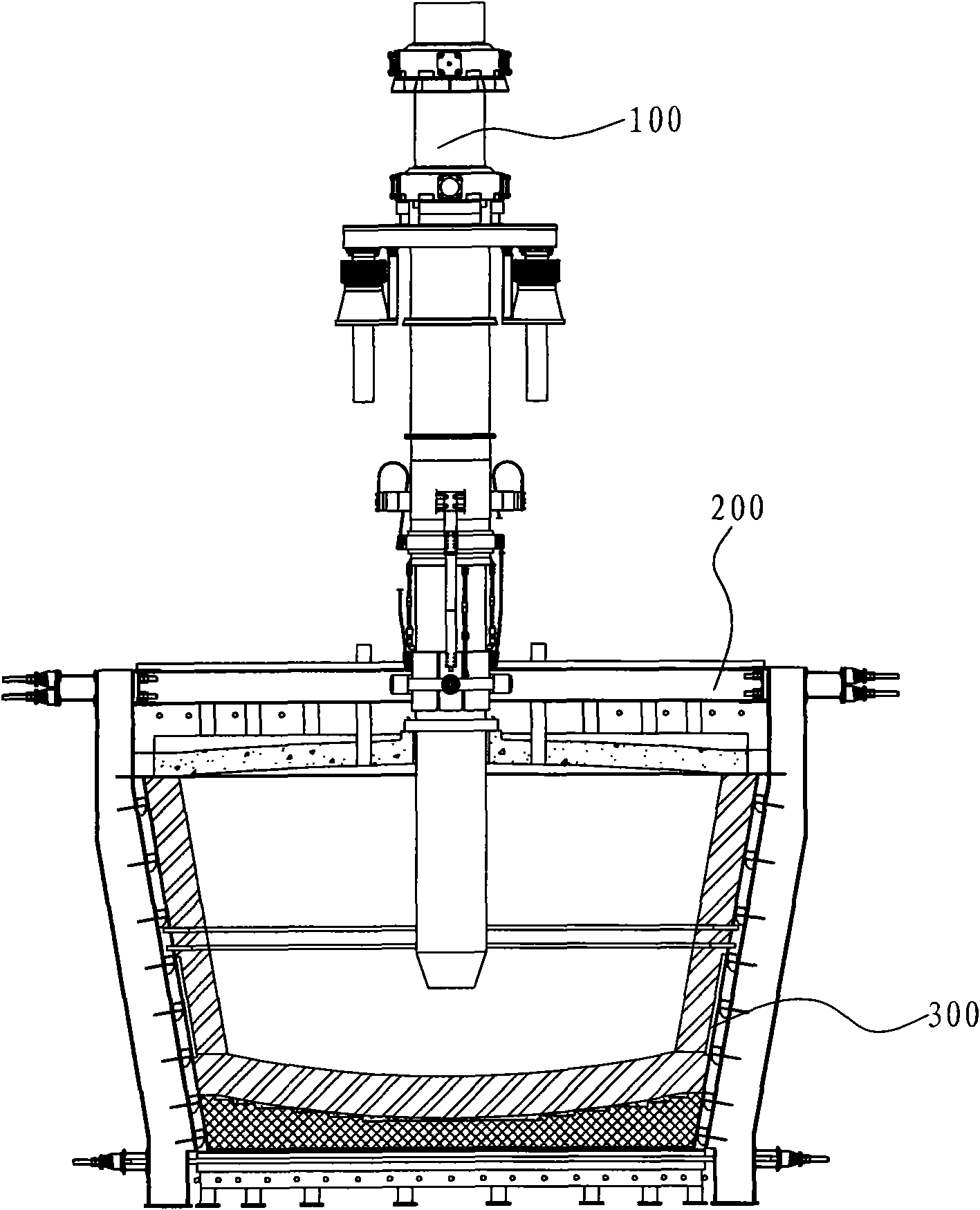
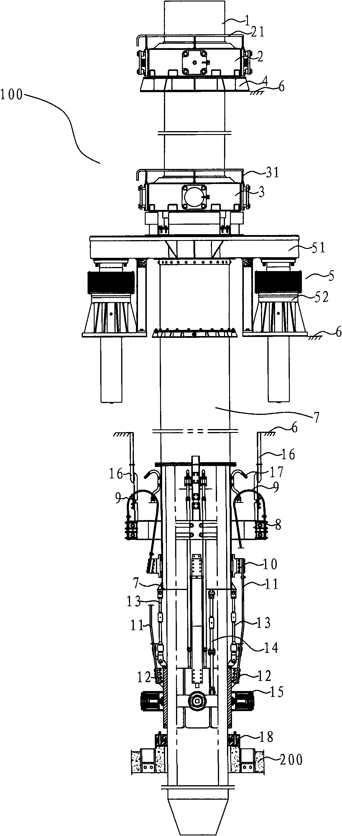
[0035] Such as Figure 1-3 As shown, the electrode device 100 according to the embodiment of the present invention is arranged above the electric furnace body 300, more specifically, the furnace body 300 also includes a furnace cover 200, and the furnace cover 200 covers the upper opening of the furnace body 300 for sealing The furnace body 300, here, the furnace cover 200 is described as a pa...


PUM


Abstract

The invention discloses an electrode device, comprising an electrode main body, an upper band-type brake, a lower band-type brake, a lifting mechanism and a conductive mechanism. The upper band-type brake is used for tightly holding and releasing the electrode main body; the lower band-type brake is used for tightly holding and releasing the electrode main body, located below the upper band-type brake, installed on the lifting mechanism and moves together with the lifting mechanism; and the conductive mechanism electrically contacts with the electrode main body and synchronously moves along with the lifting mechanism relative to the electrode main body. The electrode device is convenient to compensate the consumption quantity of the electrode and has high operation efficiency.

Description

technical field [0001] The invention relates to an electrode device, in particular to an electrode device for an electric furnace. Background technique [0002] The electric furnace is a widely used metallurgical equipment. The electrodes of the electric furnace are set above the furnace body and extend into the electric furnace. In order to adapt to different working conditions, the depth of the electrodes inserted into the furnace body needs to be adjusted frequently, so the electrodes of the electric furnace are usually movable. [0003] The traditional electric furnace usually uses a hoisting device to lift the electrode, and the cables of the hoisting device are hung on both ends of the electrode holding device, so as to realize the lifting of the electrode. In addition, there is also an electric furnace that uses a spiral lifting device to lift the electrode. The electrode is fixed on the spiral lifting device as a whole, and the electrode moves up and down with the li...

Claims


Application Information

Patent Timeline
IPC IPC(8): F27D11/10
Inventor 曹珂菲胡立琼冯晓梅李栋朱让贤张振民
Owner CHINA ENFI ENGINEERING CORPORATION
Learn More