
Concrete mixer and lubrication oil supply control system and method thereof

A technology for a concrete mixer and a control method, which is applied to chemical instruments and methods, clay preparation devices, cement mixing devices, etc., can solve problems such as reduced work efficiency, waste of lubricating oil, and impact on concrete quality, so as to avoid waste and ensure service life. Effect

Active Publication Date: 2010-07-07
SANY HEAVY IND CO LTD (CN)
View PDF6 Cites 9 Cited by
  • Summary
  • Abstract
  • Description
  • Claims
  • Application Information

AI Technical Summary

Problems solved by technology

[0008] However, when the continuous oil supply method is used to supply lubricating oil to the concrete mixer, the lubricating oil pump has been supplying oil to the parts of the concrete mixer that need to be lubricated, and when the concrete mixer is in an idling state, the parts that need to be lubricated in the machine do not need too much lubricating oil , resulting in a large waste of lubricating oil, resulting in an increase in the cost of using the concrete mixer, polluting the environment, and affecting the quality of concrete; at the same time, due to the increased consumption of lubricating oil, frequent oiling is required during the work process, resulting in a decrease in work efficiency. reduce
[0009] When the periodic oil supply method is used to supply lubricating oil to the concrete mixer, the lubricating oil pump supplies oil to the lubricated parts of the concrete mixer according to the preset rules, but during the working process of the concrete mixer, the change of its working state is not necessarily Changes are made completely according to the predetermined rules. In this way, it is easy to cause the oil supply state of the lubricating oil pump to not correspond to the working state of the concrete mixer. It may occur that when the concrete mixer is in the stirring state, the lubricating oil pump does not supply oil and the concrete mixer is idling. state, the lubricating oil pump supplies oil, resulting in the wear of parts that need to be lubricated or the waste of lubricating oil

Method used


Image

  • Concrete mixer and lubrication oil supply control system and method thereof
  • Concrete mixer and lubrication oil supply control system and method thereof
  • Concrete mixer and lubrication oil supply control system and method thereof

Examples


Embodiment Construction

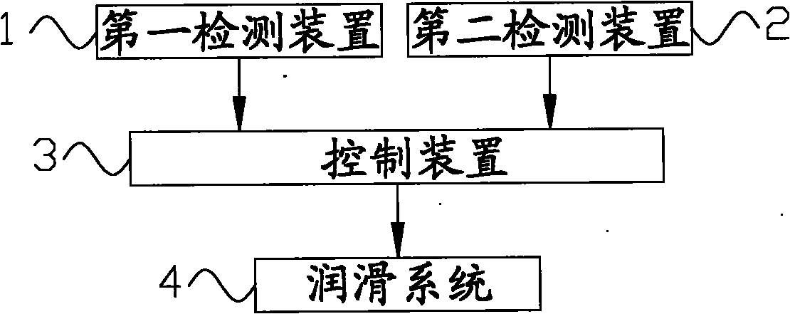
[0047] The core of the present invention is to provide a lubricating oil supply control method for a concrete mixer, which can reduce the waste of lubricating oil and further reduce the use cost on the basis of ensuring the lubricating performance and sealing performance requirements of the concrete mixer. Another core of the present invention is to provide a lubricating oil supply control system and a concrete mixer including the above lubricating oil supply control system.

[0048] In order to enable those skilled in the art to better understand the solution of the present invention, the present invention will be further described in detail below in conjunction with the accompanying drawings and specific embodiments.

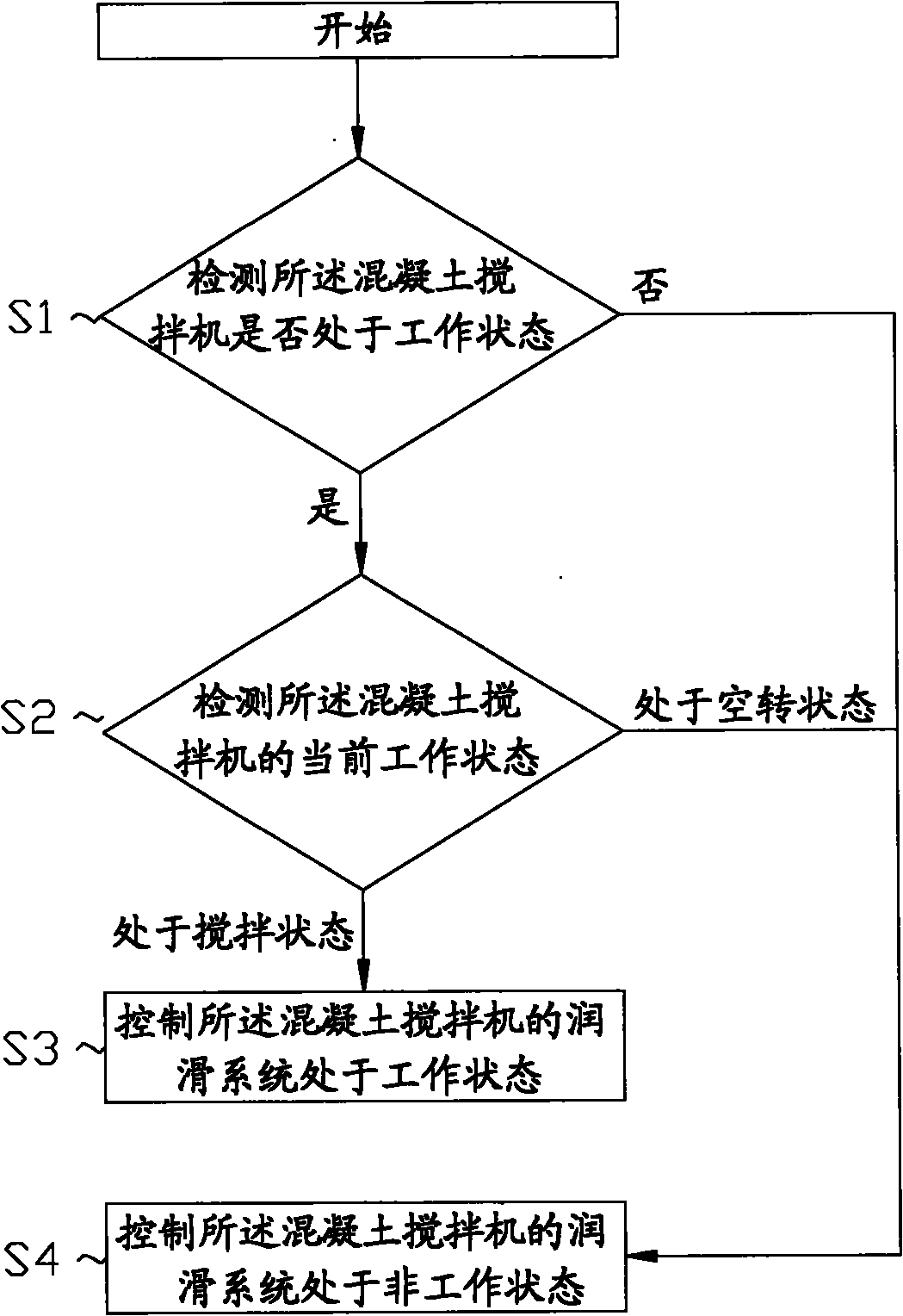
[0049] Please refer to figure 1 , figure 1 It is a schematic flowchart of the lubricating oil supply control method provided by the first specific embodiment of the present invention.

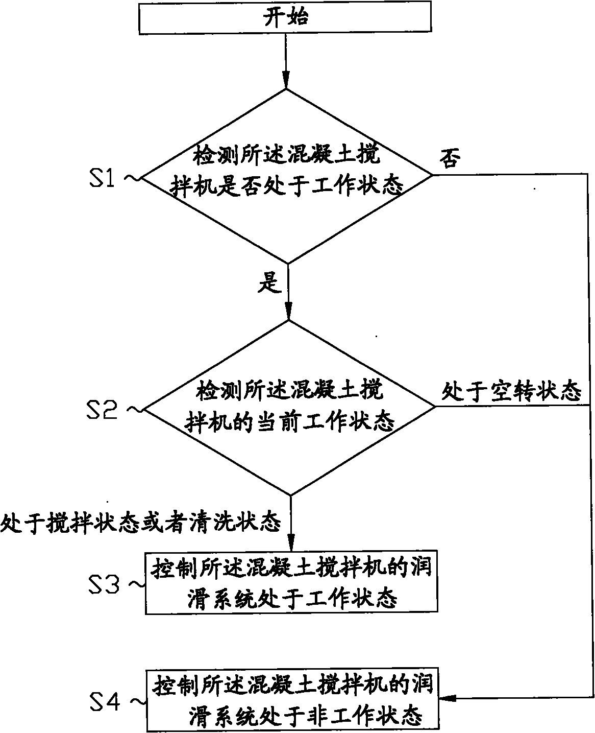
[0050] Such as figure 1 As shown, the lubricating oil control method fo...


PUM


Abstract

The invention discloses a lubricating oil supply control method, which is used for a concrete mixer and controlling the work of a lubricating system according to the work state of the concrete mixer; when the concrete mixer is in a mixing state, the lubricating oil supply control method is used for controlling the lubricating system of the concrete mixer to be in the work state; and when the concrete mixer is in an idle state, the lubricating oil supply control method is used for controlling the lubricating system of the concrete mixer to be in the non-work state. The lubricating oil supply control method not only ensures the requirements of the concrete mixer on the lubricating performance and the sealing performance, but also avoids the waste of lubricating oil caused by the lubricationwhen lubricating oil supply is not required and reduces the using cost. The invention also discloses a lubricating oil supply control system and the concrete mixer comprising the lubricating oil supply control system.

Description

technical field [0001] The invention relates to the field of concrete mixing equipment, in particular to a lubricating oil supply control method for a concrete mixer. The present invention also relates to a lubricating oil supply control system and a concrete mixer comprising the aforementioned lubricating oil control system. Background technique [0002] During the use of the concrete mixer, a large number of parts will move relative to each other, which will cause friction and seriously affect the service life of the concrete mixer. Therefore, it is very important to add lubricating oil between the parts that generate relative movement. [0003] During operation, it is generally necessary to regularly check the lubricating oil pump and fill up the lubricating grease to ensure the lubricating performance and sealing performance between the parts that move with each other. [0004] In the prior art, the following two methods are mainly used to add lubricating oil between th...

Claims


Application Information

Patent Timeline
Patent Type & Authority Applications(China)
IPC IPC(8): B27C7/00B28C5/00
Inventor 黄向阳沈明星代青龙康颖
Owner SANY HEAVY IND CO LTD (CN)
Learn More