Regulating device of belt wheel

An adjustment device and pulley technology, applied in the field of machinery, can solve the problems of not having adjustable driven wheels, unstable sliding of coupling parts, and uncertain sliding distance and position, so as to achieve precise adjustment, change of cutting angle, and increase of adjustable sexual effect

Active Publication Date: 2010-07-07
陈文满
View PDF12 Cites 14 Cited by
  • Summary
  • Abstract
  • Description
  • Claims
  • Application Information

AI Technical Summary

Problems solved by technology

Although the above-mentioned structure can adjust the angle of the abrasive belt, it still has certain defects: 1. There is no mechanism for adjusting the circumferential rotation of the driven wheel in this device, that is, the balance between the driven wheel and the driving wheel or the tensioner wheel cannot be adjusted. degree, which inevitably increases the requirements achieved by the installation
2. The base is the frame of the polishing machine, which makes it inconvenient to process the groove and also limits the fixed range of the driven wheel
3. When the connecting piece needs to slide axially along the vertical shaft, there is no auxiliary mechanism to push it, which leads to problems such as unstable sliding of the connecting piece and uncertainty of the sliding distance and position.

Method used


Image

  • Regulating device of belt wheel
  • Regulating device of belt wheel
  • Regulating device of belt wheel

Examples


Embodiment 1

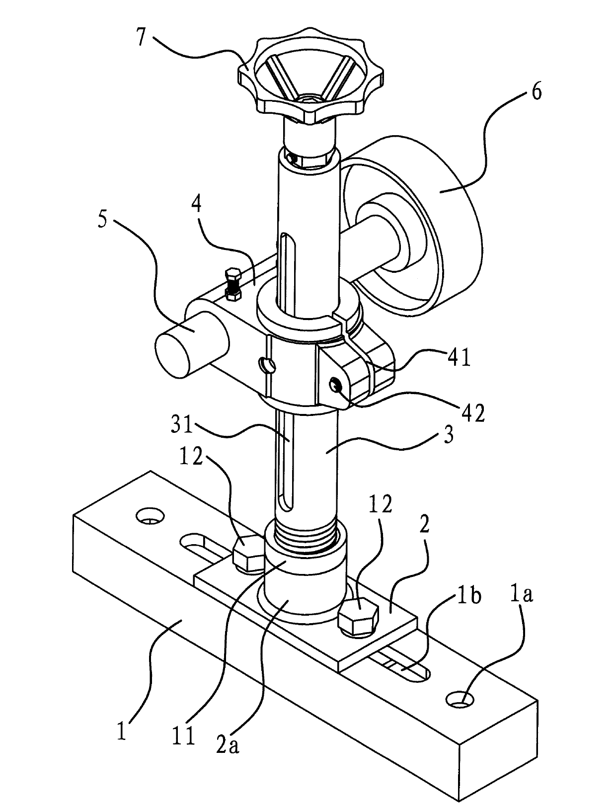
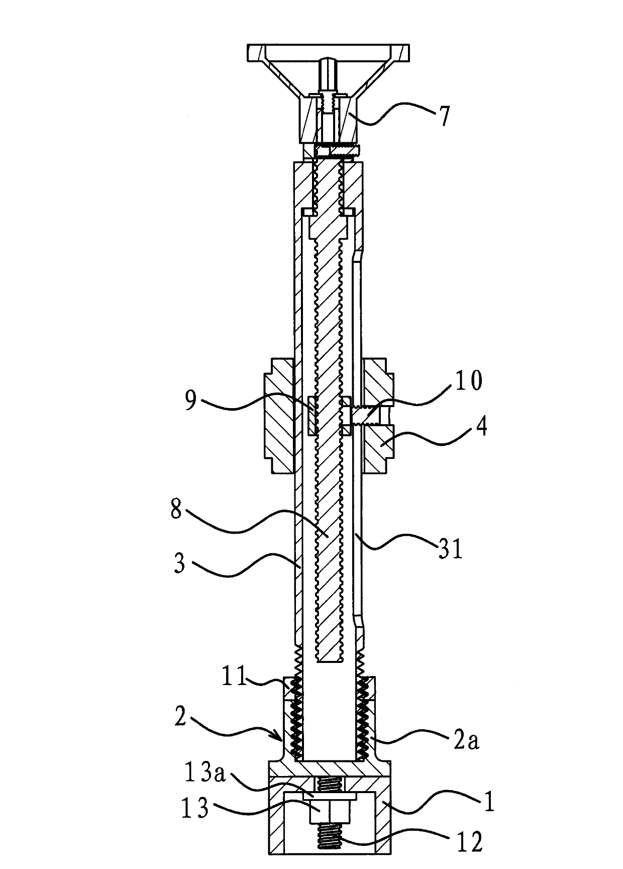
[0025] Such as figure 1 As shown, the adjusting device of the pulley comprises a base 1, a positioning part 2, a vertical shaft 3, a rotating shaft 5, a pulley 6 and a coupling part 4. The adjusting device is used for adjusting various types of belt drives, generally it is used for belt polishing machines.

[0026] Specifically, the base 1 is in the shape of a strip, and is generally provided with fixing holes 1a at both ends thereof; bolts 12 and other connecting parts pass through the fixing holes 1a to fix the base 1 on the frame or base of the polishing machine or on the ground, The abrasive belt is sheathed on the pulley 6, thus drawing, the way that the regulating device is fixed has diversity and the extensiveness of the fixed position.

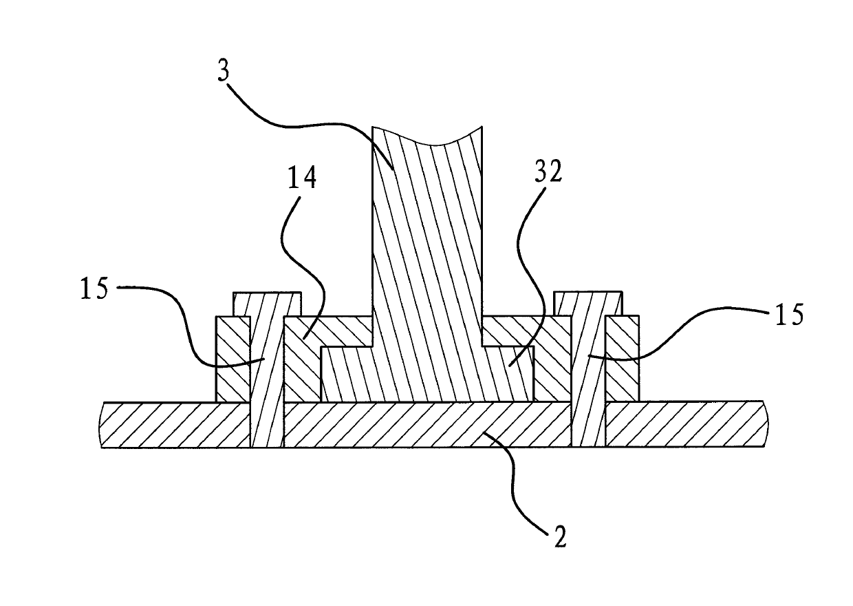
[0027] The base 1 is made of channel steel and has a linear guide groove 1b on the waist surface, and the vertical axis 3 is perpendicular to the waist surface of the base 1 . A sheet-shaped positioning piece 2 is provided on the low...

Embodiment 2

[0036] The structure and principle of this embodiment are basically the same as those of the first embodiment, except that the positioning member 2 is fixedly connected to the base 1 or the above-mentioned positioning cap 2a is fixedly connected to the base 1 . Therefore, among the three steps of the above-mentioned adjustment process, only steps 2 and 3 can be operated.

Embodiment 3

[0038] The structure and principle of this embodiment are basically the same as that of the first embodiment, except that the lower end of the vertical shaft 3 is fixedly connected to the positioning member 2 . Therefore, among the three steps of the above-mentioned adjustment process, only steps 1 and 3 can be operated.


PUM


Abstract

The invention provides a regulating device of belt wheel, belonging to the technical field of machinery, and solving the problem that the existing regulating device of belt wheel is not provided with a mechanism for regulating a driven wheel to rotate circumferentially. The regulating device of belt wheel comprises a seat and a vertical shaft vertically arranged on the seat, a spindle is arranged on the vertical shaft perpendicular to the vertical shaft, a belt wheel is sheathed on the spindle, and a positioning mechanism capable of causing the vertical shaft to do rectilinear translation and / or rotation regulation along the seat and positioning the vertical shaft after regulation is finished. The vertical shaft of the regulating device of belt wheel does rectilinear translation and / or rotation regulation and the spindle can move along the axial direction of the vertical shaft, the spindle, the vertical shaft and the regulating device can be regulated individually or jointly to drive the belt wheel to move to regulate the belt wheel to a proper position more conveniently, and the invention has the advantage of convenient, exact and stable regulating.

Description

technical field [0001] The invention belongs to the technical field of machinery, and in particular relates to a pulley adjusting device. Background technique [0002] In a belt polisher, the abrasive belt is sleeved on the driving wheel and the driven wheel. When the abrasive belt polishing machine polishes the object, it relies on the motor to drive the driving wheel, so that the abrasive belt rotates at a high speed, rubs the surface of the object, and completes the polishing process. During the use of the polishing machine, due to the different positions of the surface of the workpiece, the size of the workpiece, and the requirements for polishing the workpiece, the cutting angle of the workpiece by the abrasive belt needs to change to a certain extent. In the existing polishing machine, the machine body, the driving wheel and the driven wheel are all fixed, so the cutting angle of the abrasive belt cannot be adjusted, which brings difficulties to the processing of work...

Claims


Application Information

Patent Timeline
Patent Type & Authority Applications(China)
IPC IPC(8): B24B21/20
Inventor 陈美青
Owner 陈文满
Why Eureka
Try Eureka