Gear shifting mechanism of harvester
A gear shifting mechanism and harvester technology, applied to mechanical equipment, components with teeth, belts/chains/gears, etc., can solve problems such as difficult shifting, difficult shifting, and many intermediate links
Inactive Publication Date: 2010-06-30
河南蛮牛农机制造有限公司
View PDF0 Cites 1 Cited by
- Summary
- Abstract
- Description
- Claims
- Application Information
AI Technical Summary
Problems solved by technology
[0002] The shift mechanism on the existing harvester is connected to the gearbox through the shift assembly and bracket, short shift lever, short pivot arm, long shift lever and shift pivot arm. Due to the large number of intermediate links and large gaps, it often occurs The phenomenon that the gear is not easy to be engaged and the gear is not easy to change, which affects the work efficiency
Method used
View moreImage
Smart ImageViewing Examples
Examples
Embodiment Construction
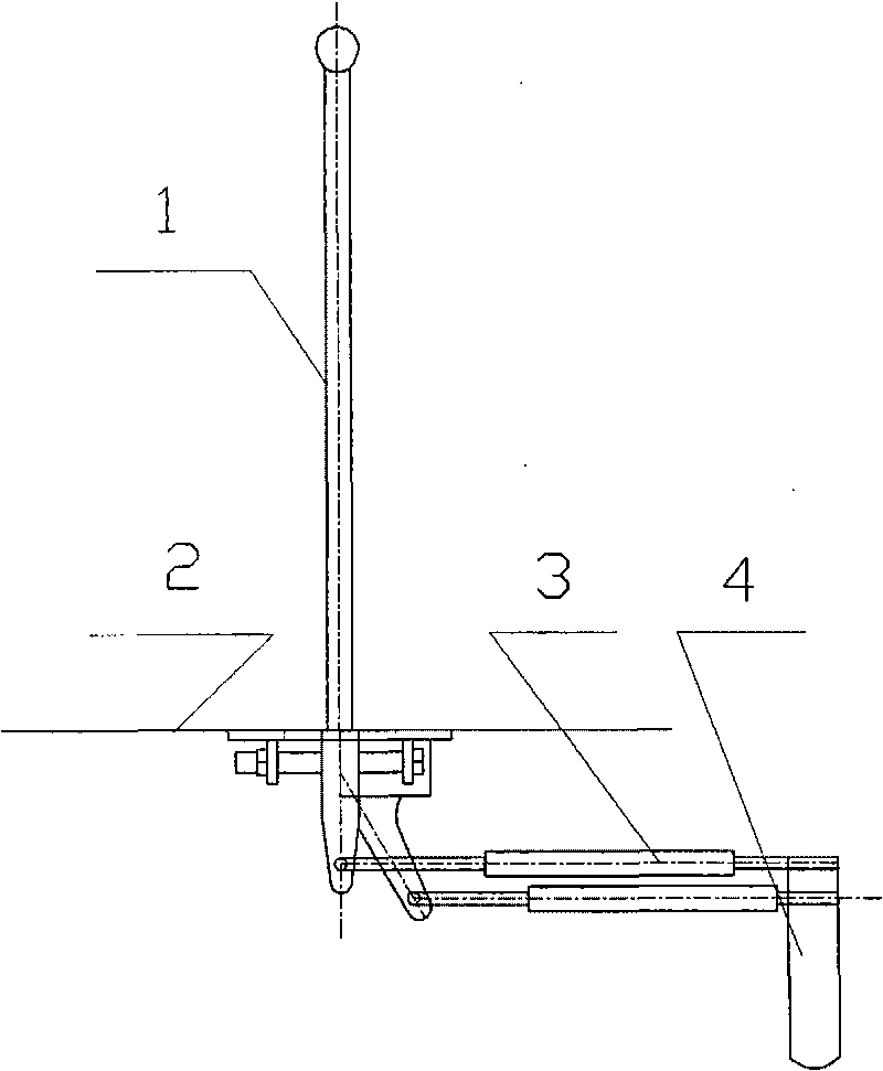
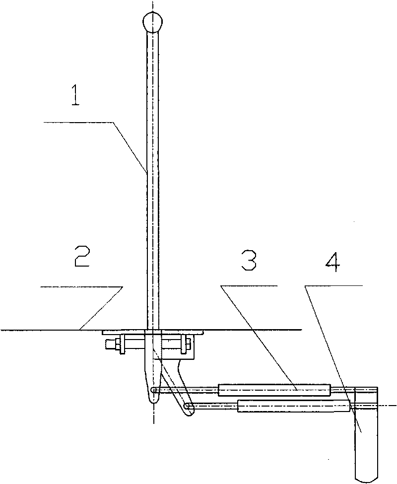
[0006] The present invention will be further described in detail with reference to the accompanying drawings. The gear lever assembly 1 fixed on the connecting platform 2 is movably connected to one end of the shift link 3, and the other end of the shift link 2 is movable with the shift arm 4 Connected together, the shift arm 4 is connected with the gearbox.
Login to View More PUM
 Abstract
The invention discloses a gear shifting mechanism of a harvester. The purpose of the invention is to provide a gear shifting mechanism of a harvester with convenient and easy gear shifting. The technical scheme of the invention includes that: the gear shifting mechanism of the harvester comprises a gear shifting assembly, a gear shifting pull rod and a gear shifting rotary arm, the gear shifting assembly is movably connected with one end of the gear shifting pull rod, while the other end of the gear shifting pull rod is movably connected with the gear shifting rotary arm. The gear shifting mechanism has the technical effects that: as only the gear shifting pull rod is arranged between the gear shifting assembly and the gear shifting rotary arm, the intermediate power conversion steps are reduced, the gear shifting assembly can easily transfer the gear shifting power to the gear shifting pull rod and the gear shifting rotary arm, thereby ensuring more convenient and easier gear shifting.
Description
Technical field [0001] The invention relates to a gear shift mechanism on a vehicle, particularly a gear shift mechanism on a harvester. Background technique [0002] The shift mechanism on the existing harvester is connected to the gearbox through the shift assembly and bracket, short shift lever, short boom, long shift lever and shift boom. Due to the large number of intermediate links and large gaps, it often occurs The phenomenon of poor shifting and poor shifting affects work efficiency. Summary of the invention [0003] The purpose of the present invention is to provide a gear shifting mechanism on a harvester that is convenient and easy to shift. The technical scheme of the present invention is completed in this way. The shift mechanism on the harvester includes a shift assembly, a shift lever, and a shift arm. The feature is that the shift assembly is movably connected to one end of the shift link, The other end of the shift lever is movably connected with the shift arm....
Claims
Login to View More Application Information
Patent Timeline
 Patent Type & Authority Applications(China)
IPC IPC(8): F16H59/04
Inventor 堵纯乾
Owner 河南蛮牛农机制造有限公司
Features
- R&D
- Intellectual Property
- Life Sciences
- Materials
- Tech Scout
- Unparalleled Data Quality
- Higher Quality Content
- 60% Fewer Hallucinations
Learn More Browse by: Latest US Patents, China's latest patents, Technical Efficacy Thesaurus, Application Domain, Technology Topic, Popular Technical Reports.
© 2025 PatSnap. All rights reserved.Legal|Privacy policy|Modern Slavery Act Transparency Statement|Sitemap|About US| Contact US: help@patsnap.com


