
Omnidirectional automobile carrying device

A technology for handling devices and automobiles, which is applied in the direction of buildings, building types, and buildings where cars are parked to achieve good support effects.

Inactive Publication Date: 2010-06-30
金华法
View PDF1 Cites 20 Cited by
  • Summary
  • Abstract
  • Description
  • Claims
  • Application Information

AI Technical Summary

Problems solved by technology

[0004] The purpose of the present invention is to solve the problem that the clamping tire handling device of the three-dimensional garage can only be transported in one direction, and to provide an omnidirectional vehicle handling device that can be transported in any direction and can rotate in situ

Method used


Image

  • Omnidirectional automobile carrying device
  • Omnidirectional automobile carrying device
  • Omnidirectional automobile carrying device

Examples


Embodiment 1

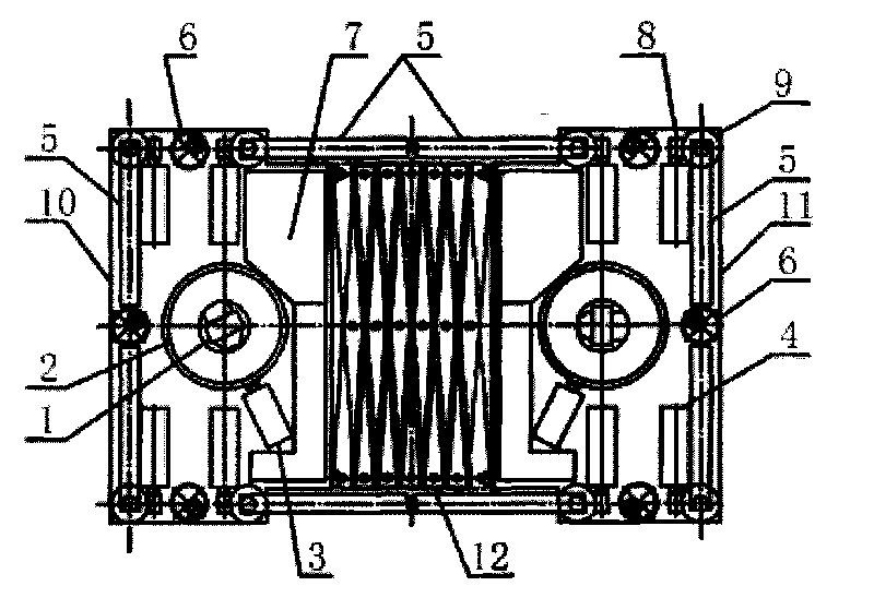
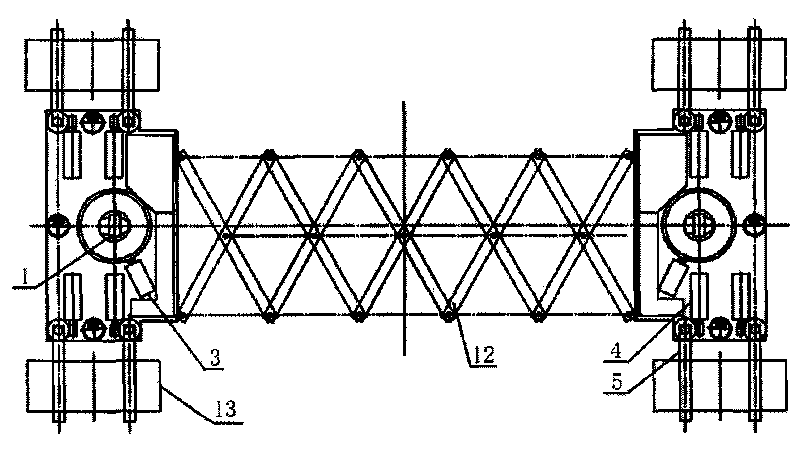
[0023] Embodiment 1: a kind of omnidirectional automobile handling device (as figure 1 shown). The device comprises a front frame 10 and a rear frame 11, the rear side of the front frame 10 and the front side of the rear frame 11 are connected by a telescopic link 12 which can be freely retracted, and the front frame 10 and the rear frame 11 Since the structure is symmetrical, the structure of the front frame 10 will be described below. Intelligent controller 7 is installed in the rear portion of front vehicle frame 10, and the front side and left and right sides of front vehicle frame 10 are provided with universal driven wheel 6 respectively, and the left and right sides of front vehicle frame 10 are respectively hinged with two clamping arms 5, The clamp arms 5 on the left and right sides are installed symmetrically, and two clamp arms 5 on each side form a group of clamp arms for holding and clamping a car wheel 13. The outside of the hinge point of the clamp arms 5 is th...

Embodiment 2

[0028] Embodiment 2: a kind of omnidirectional vehicle handling device (as Figure 5 shown). The device comprises a front frame 10 and a rear frame 11, the rear side of the front frame 10 and the front side of the rear frame 11 are connected by a telescopic link 12 which can be freely retracted, and the front frame 10 and the rear frame 11 Since the structure is symmetrical, the structure of the front frame 10 will be described below. Intelligent controller 7 is installed in the rear portion of front vehicle frame 10, and four sides of front vehicle frame 10 are all provided with universal driven wheel 6, and the left and right sides of front vehicle frame 10 are respectively hinged with two clip arms 5, and left and right two The clamp arms 5 on the side are installed symmetrically, and two clamp arms 5 on each side form a group of clamp arms for holding and clamping a car wheel 13. The clamp arms 5 fix the clamp arm connecting rod 20 at the hinge point, and the clamp arm co...


PUM


Abstract

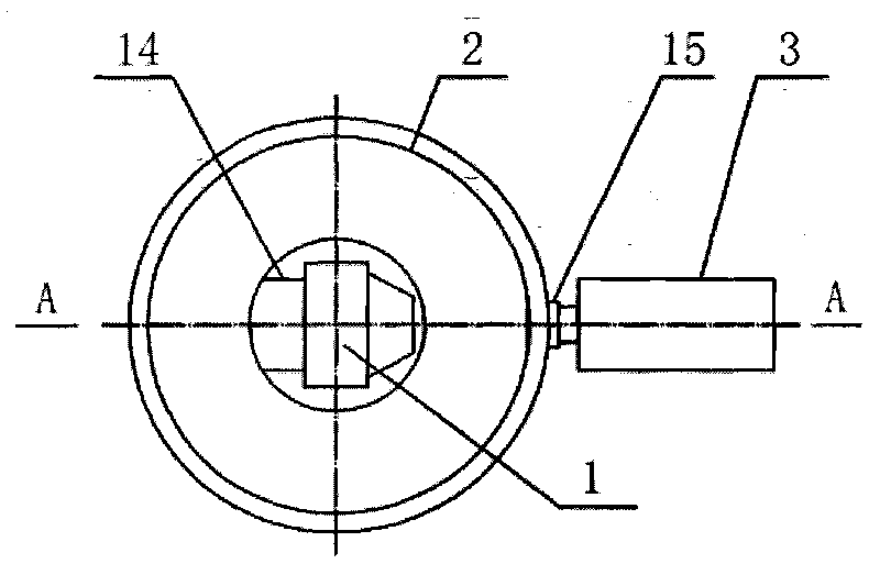
The invention relates to an automobile carrying device, in particular to an omnidirectional automobile carrying device, which solves the problem that a tyre clamping carrying device of a three-dimensional garage can carry automobiles only along one direction. The automobile carrying device comprises a frame, clamping arms, a traveling mechanism and an intelligent controller, wherein the clamping arms, the traveling mechanism and the intelligent controller are arranged on the frame. The automobile carrying device is characterized in that the traveling mechanism comprises drive wheels capable which can adjust a traveling direction, and a plurality of universal driven wheels; a pedestal is fixed on the frame; the pedestal is provided with steering frames rotating relative to the pedestal; the drive wheels are fixed on the steering frames; and axes of the drive wheels are vertical to and intersect with rotating axes of the steering frames. In the invention, the omnidirectional movement of the whole carrying device is realized, and the direction of the carrying device can be changed at any angle; and telescopic connecting rods are arranged between a front frame and a rear frame so as to adjust the length of the carrying device according to differences in wheel bases of front and rear wheels of the automobiles.

Description

technical field [0001] The invention relates to a vehicle handling tool, in particular to an omnidirectional vehicle handling device. technical background [0002] With the increase of the number of vehicles, three-dimensional garages are built in many places to solve the problem of parking difficulties. Most of the vehicles in the three-dimensional garages are transported in three ways, the vehicle-carrying plate handling, the comb-like handling device, and the clamping tire handling device. transport. The way of clamping the tire is to drill the carrier under the car, and use the clamping device to hold the wheel to lift the car and carry it. The existing clamping tire handling device generally can only be transported in a single direction, generally enters the bottom of the vehicle from the front or rear of the vehicle, lifts the car and transports it along the direction of the front or rear of the vehicle and along the track, the other directions of the garage Handling...

Claims


Application Information

Patent Timeline
IPC IPC(8): E04H6/28E04H6/40
Inventor 金华法
Owner 金华法
Learn More