
Balanced connection mechanism for finishing mill bracket

A technology of balanced connection and finishing mill, applied in the direction of metal rolling stand, metal rolling mill stand, metal rolling, etc., can solve problems affecting rolling stability, large bracket vibration, stop production, etc., to achieve outstanding substantive Features, Effects of Preventing Changes in Roll Gap

Inactive Publication Date: 2010-06-30
SHANDONG XIWANG SPECIAL STEEL
View PDF0 Cites 1 Cited by
  • Summary
  • Abstract
  • Description
  • Claims
  • Application Information

AI Technical Summary

Problems solved by technology

If the vibration of the two brackets causes the chain to loosen, the chain will not be able to transmit force and lose the ability to control the balance of the two brackets, resulting in excessive vibration of the brackets, which will change the distance between the rolls and affect the rolling process. In severe cases, it may even cause damage to the bracket bearing or roll bearing and cause production stoppage. This is the shortcoming of the existing technology

Method used


Image

  • Balanced connection mechanism for finishing mill bracket
  • Balanced connection mechanism for finishing mill bracket

Examples


Embodiment Construction

[0008] In order to clearly illustrate the technical features of the solution, the solution will be described below through a specific implementation mode combined with the accompanying drawings.

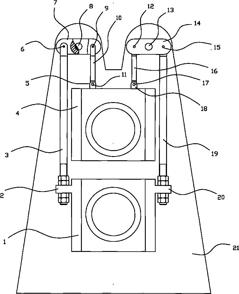
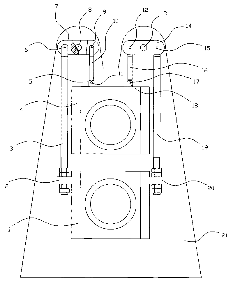
[0009] It can be seen from the accompanying drawings that the bracket balance connection mechanism of the finishing mill in this program has a frame 21, an upper bracket 4 and a lower bracket 1, and the upper bracket 4 has an upper bracket left mounting ear 5 and an upper bracket Right mounting ear 18, lower bracket left mounting ear 2 and lower bracket right mounting ear 20 are arranged on lower bracket 1, left central axis 8 and right central axis 13 are arranged on frame 21 above upper bracket 4, and , the axis of the left central shaft 8 and the axis of the right central shaft 13 are on the same horizontal plane. This scheme is that the left lever 7 is housed on the left central axis 8, and the left lower link 3 is connected with the left lower link connecting shaft 6 on the left...


PUM


Abstract

The invention provides a technical scheme of a balanced connection mechanism for a finishing mill bracket, which is characterized in that: a left lever is arranged on a left central shaft; a left lower connecting rod is connected on the left side of the left lever through a connecting shaft of the left lower connecting rod. T; the left lower connecting rod and a left mounting lug of a lower bracket are in adjustable fixed connection; a left upper connecting rod is connected on the right side of the left lever through a connecting shaft of the left upper connecting rod; the left upper connecting rod is connected with the left mounting lug of an upper bracket through the connecting shaft of the left lug of the upper bracket; a right lever is arranged on a right central shaft; a right lower connecting rod is connected on the right side of the right lever through a connecting shaft of the right lower connecting rod; the right lower connecting rod and a right mounting lug of a lower bracket are in adjustable fixed connection; a right upper connecting rod is connected on the left side of the right lever through a connecting shaft of the right upper connecting rod; the right upper connecting rod is connected with a right mounting lug of the upper bracket through the right lug of the upper bracket; the distance between the axis of the connecting shaft of the left lower connecting rod and the axis of the left central shaft and between the axis of the connecting shaft of the left upper connecting rod and the axis of the left central shaft is equal to the distance between the axis of the connecting shaft of the right lower connecting rod and the axis of the right central shaft and between the axis of the connecting shaft of the right upper connecting rod and the axis of the right central shaft.

Description

Technical field: [0001] The invention relates to a mechanism for a steel rolling mill in the metallurgical industry, in particular to a balanced connection mechanism for a finishing mill bracket. Background technique: [0002] In the prior art, the well-known technology is the balanced connection mechanism of the finishing mill bracket in use. The existing mechanism uses two chains, left and right, to connect the upper bracket and the lower bracket. However, the transmission of the chain can only transmit pull, but not push. Therefore, when the two brackets vibrate, only when the chain is tightened in the direction of movement, the chain will play the role of force transmission to keep the two brackets in balance and reduce their vibration. If the vibration of the two brackets loosens the chain, the chain cannot transmit force and loses the ability to control the balance of the two brackets, resulting in excessive vibration of the brackets, changing the distance between the...

Claims


Application Information

Patent Timeline
Patent Type & Authority Applications(China)
IPC IPC(8): B21B31/04
Inventor 王勇王栋高涛张平易
Owner SHANDONG XIWANG SPECIAL STEEL
Learn More