Method for detecting output current of inverting welding machine

A technology of output current detection and inverter welding machine, applied in the direction of measuring current/voltage, measuring device, measuring electrical variables, etc., can solve the problems of high cost, low cost and complex detection circuit of Hall current sensor

Active Publication Date: 2012-09-05
HANGZHOU KAIERDA ELECTRIC WELDING MACHINE
View PDF0 Cites 0 Cited by
  • Summary
  • Abstract
  • Description
  • Claims
  • Application Information

AI Technical Summary

Problems solved by technology

The advantage of the Hall current sensor is to realize the isolation of the detection circuit from the main circuit, but the cost of the Hall current sensor is high, especially the high current Hall sensor; and the Hall current sensor needs power supply, and the detection circuit is complex
The cost of using the shunt is low, but it cannot realize the isolation between the detection circuit and the main circuit, and the anti-interference ability is poor
This is the shortcoming of the current detection method for the output current of the inverter welding machine.

Method used


Image

  • Method for detecting output current of inverting welding machine
  • Method for detecting output current of inverting welding machine
  • Method for detecting output current of inverting welding machine

Examples


Embodiment Construction

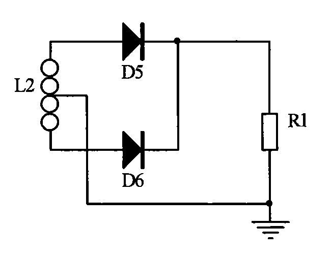
[0009] According to attached figure 1 The circuit configuration of the present invention will be described. The current transformer L1 is placed on the primary (or secondary) of the main transformer, detects the primary (or secondary) current of the transformer, and rectifies the current sampled by L1 through a bridge rectifier circuit composed of rectifier diodes D1, D2, D3 and D4 After being sampled by the resistor R1, the voltage is divided by the resistors R2 and R3, and the voltage value of R3 is proportional to the primary current of the main transformer. The noninverting input terminal (pin 4) of the voltage comparator U1A is connected to R3, and the input terminal (pin 5) of the inverting terminal is connected to the output resistor R6. When the voltage of R3 is higher than the voltage of resistor R6, the output terminal (pin 2) of the voltage comparator U1A will have a low level to turn on Q1, so that the voltage source VCC charges the filter capacitor C1 through R5 ...


PUM


Abstract

The invention relates to a method for detecting the output current of an inverting welding machine, which mainly comprises the current sampling step and the single processing step. A current transformer L1 is arranged in the primary or secondary grade of a main transformer, a bridge-type rectifying circuit which is formed by a diode D1, a diode D2, a diode D3 and a diode D4 is used for rectifyingthe current sampled by the current transformer L1, a resistor R1 is used for sampling, and a resistor R2 and a resistor R3 are used for dividing the voltage. The in-phase input end of a voltage comparator U1A is connected with the resistor R3, and the inverted-phase input end is connected with an output resistor R6. When the voltage of the resistor R3 is higher than the voltage of the output resistor R6, the output end of the voltage comparator U1A is in the low level to energize a P-type or N-type switching pipe Q1 to enable a voltage source VCC to charge a filter capacitor C1. When the voltage of the resistor R3 is lower than the voltage of the output resistor R6, the output end of the voltage comparator U1A is in the high level to deenergize the P-type or N-type switching pipe Q1 to enable a voltage source VCC to stop charging the filter capacitor C1 so that the voltage of the output resistor R6 is kept to be the peak voltage of the resistor R3. Because the peak voltage of the resistor R3 is in direct proportion to the output current of the inverting welding machine, the voltage of the output resistor R6 is in direct proportion to the output current of the inverting welding machine. The method for detecting the output current of the inverting welding machine is characterized in that the current is sampled in the primary or secondary grade of the main transformer rather thanon the output end of the main transformer.

Description

Technical field: [0001] The invention relates to an electric welding machine, especially a method for detecting the output current of an inverter electric welding machine. Background technique: [0002] In order to accurately control the welding current, the inverter welding machine needs to detect the output current of the welding machine in real time. At present, devices such as Hall current sensors or shunts are used to detect the output current of the welding machine at the output end of the welding machine. The advantage of the Hall current sensor is to realize the isolation of the detection circuit from the main circuit, but the cost of the Hall current sensor is high, especially the high current Hall sensor; and the Hall current sensor needs power supply, and the detection circuit is complicated. The cost of the scheme using the shunt is low, but the isolation between the detection circuit and the main circuit cannot be realized, and the anti-interference ability is p...

Claims


Application Information

Patent Timeline
Patent Type & Authority Patents(China)
IPC IPC(8): G01R19/00
Inventor 侯润石王进成兰照丹褚华李振升董俊娟王辉
Owner HANGZHOU KAIERDA ELECTRIC WELDING MACHINE
Why Eureka
Try Eureka