Back plate for plasma display

A plasma display and backplane technology, applied in the direction of solid cathode components, etc., can solve the problem of poor size adaptability and achieve the effect of improving size adaptability

Inactive Publication Date: 2010-06-09
SICHUAN COC DISPLAY DEVICES
View PDF0 Cites 3 Cited by
  • Summary
  • Abstract
  • Description
  • Claims
  • Application Information

AI Technical Summary

Problems solved by technology

[0004] The present invention aims to provide a backplane for a plasma display, which can solve the problem that the backplane in the prior art has poor adaptability to PCB size

Method used


Image

  • Back plate for plasma display
  • Back plate for plasma display

Examples


Embodiment Construction

[0017] The present invention will be described in detail below with reference to the accompanying drawings and in combination with embodiments.

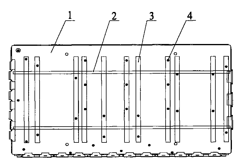
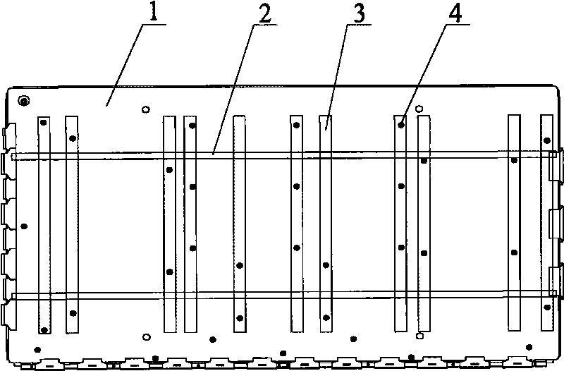
[0018] figure 1 A schematic structural view of a backplane for a plasma display according to a preferred embodiment 1 of the present invention is shown, the backplane includes: a guide rail 2, which is horizontally fixed on the backplane 1; a slide rail 3, which is longitudinally located on the guide rail 2, Suitable for lateral movement along the guide rail 2; stud 4, which is installed on the slide rail 3.

[0019] Wherein, the guide rail 2 is riveted on the backboard 1 .

[0020] In this preferred embodiment, since guide rails and slide rails movable along the guide rails are set on the backplane, the studs are located on the slide rails and can move along the slide rails, the PCB can be fixed by adjusting the positions of the slide rails and studs, which solves the problem There is a problem that the technical backplane has poo...


PUM


Abstract

The invention provides a back plate for a plasma display, comprising a guide rail which is fixed on the back plate transversely; a sliding rail which is arranged on the guide rail longitudinally and moves laterally along the guide rail; and a double-screw bolt which is arranged on the sliding rail; the back plate can fix PCB with different sizes, the position of the double-screw bolt on the back plate can be adjusted continuously, so as to improve the adaptability of the back plate to the size of the PCB and realize the compatible performance of the display screen with the same specification to PCB with different sizes.

Description

technical field [0001] The present invention relates to the field of flat panel displays, in particular, to backplanes for plasma displays. Background technique [0002] At present, in the initial stage of the plasma display (Plasma Display Panel, PDP) research and development process, the connection between the used backplane and the PCB (Printed Circuit Board, printed circuit board) is riveted, that is, the screws used to fix the PCB The posts are riveted to the back plate. [0003] In the process of realizing the present invention, the inventor found that there are at least the following problems in the prior art: in the prior art, since the studs used to fix the PCB are directly riveted on the backboard, once the backboard has been processed, the The position of the studs is fixed. When the size of the PCB changes, the processed PCB cannot be installed on the backplane, so the backplane needs to be redesigned and reprocessed. Therefore, the adaptability of the backplan...

Claims


Application Information

Patent Timeline
IPC IPC(8): H01J17/16
Inventor 吕娜柴立军
Owner SICHUAN COC DISPLAY DEVICES
Why Eureka
Try Eureka