Visual polymer micro-extrusion mold

A technology for extruding molds and polymers, applied in the field of visual micro-extrusion molds, can solve problems such as unreported, and achieve the effect of avoiding easy breakage

Inactive Publication Date: 2011-10-19
DALIAN UNIV OF TECH
View PDF6 Cites 0 Cited by
  • Summary
  • Abstract
  • Description
  • Claims
  • Application Information

AI Technical Summary

Problems solved by technology

At present, mold visualization technology has become a hot spot in the field of mold research at home and abroad, mainly focusing on injection mold visualization technology, and has achieved significant research progress, but there is no report on the research on polymer micro-extrusion mold visualization technology at home and abroad.

Method used


Image

  • Visual polymer micro-extrusion mold
  • Visual polymer micro-extrusion mold

Examples


Embodiment Construction

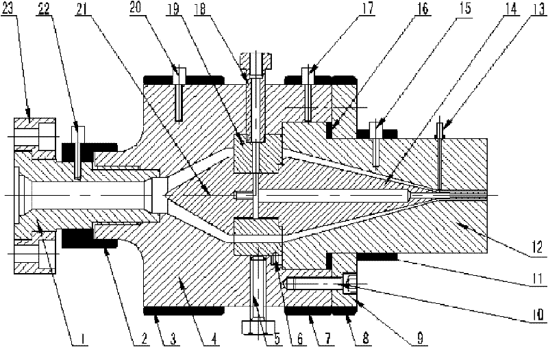
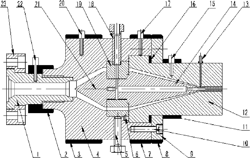
[0014] Specific embodiments of the present invention will be described in detail below in conjunction with the technical solution and the drawings.

[0015] Use A heating ring 2, B heating ring 3, C heating ring 7, D heating ring 8, E heating ring 11 to heat the mold so that the temperature of each area of ​​the mold reaches the set value. A temperature sensor 15, B temperature sensor 17, C temperature sensor 20, and D temperature sensor 22 installed on the connecting pipe 1, the head body 4 and the visualization die 12 are used to control the temperature during the extrusion process to be constant. Under the action of the screw of the extruder, the polymer melt flows into the head body 4 from the connecting pipe 1, and enters the flow channel through the split cone 21. Then, under the combined action of the mandrel 14 and the visualization die 12, the melt cross section The shape is gradually compressed to meet the design requirements, and extruded from the exit of the visualiza...


PUM


Abstract

The invention discloses a visual polymer micro-extrusion mold and belongs to the technical field of polymer micro-extrusion molds. The visual polymer micro-extrusion mold is characterized in that the visual mold consists of a connecting pipe, a heating ring, a handpiece body, an adjusting bolt, a positioning pin, a baffle, a fastening bolt, a visual neck ring mold, a pressure / temperature sensor, a core rod, a gasket, a temperature sensor, a ventilating bolt, a support plate, a spure spreader and a flange. The spure spreader, the core rod and the neck ring mold with different structural parameters are respectively exchanged according to the need; coaxiality and clearance between the core rod and the visual neck ring mold are adjusted by the method of fixing the visual neck ring mold and adjusting the core rod; the visual neck ring mold is used for observing the flow state in the micro-extrusion mold of polymer melt; the pressure / temperature sensor is used for measuring pressure and temperature of straight section of the polymer melt; and the heating ring and the temperature sensor are used for controlling temperature of the micro-extrusion mold. The visual polymer micro-extrusion mold obtains flow distribution, flow characteristics and wall slip velocity of the polymer melt in the flow channel by the visual neck ring mold.

Description

Technical field [0001] The invention belongs to the technical field of polymer micro-extrusion molds, and relates to a visual micro-extrusion mold for observing the flow field distribution and wall slip speed of polymer melt in a micro flow channel. Background technique [0002] The flow process of polymer melt in the micro runner of extrusion die has always been a key issue in die design and polymer rheology research. Traditional research methods can only use input and output parameters, such as temperature, viscosity, pressure, etc., to infer the flow process of polymer melt in micro-channels, and cannot directly describe the true flow behavior of polymer in the channel. The guiding role of mold structure design is limited. [0003] The micro-extrusion die is the key equipment for the entire micro-extrusion molding process of plastic melt. In the current micro-extrusion die design, due to the incomplete polymer rheological theory under the micro-scale effect, it is impossible t...

Claims


Application Information

Patent Timeline
Patent Type & Authority Patents(China)
IPC IPC(8): B29C47/08B29C47/12B29C47/92B29C48/92B29C48/30
CPCB29C48/92B29C2948/92209B29C2948/92409B29C2948/92704B29C2948/92019B29C2948/92514B29C2948/92904
Inventor 赵丹阳金翼飞王敏杰
Owner DALIAN UNIV OF TECH
Why Eureka
Try Eureka