Uhf reader demodulation circuit

A technology of demodulation circuit and reader, which is applied to the modulation and transformation of instruments, diodes, computer parts, etc. low gain effect

Inactive Publication Date: 2010-05-12
WUHAN WINNINGCHINA MICROSYST TECH
View PDF0 Cites 4 Cited by
  • Summary
  • Abstract
  • Description
  • Claims
  • Application Information

AI Technical Summary

Problems solved by technology

[0005] The technical problem to be solved by the present invention is to solv...

Method used


Image

  • Uhf reader demodulation circuit
  • Uhf reader demodulation circuit
  • Uhf reader demodulation circuit

Examples


Embodiment Construction

[0012] The present invention will be described in detail below in conjunction with the accompanying drawings.

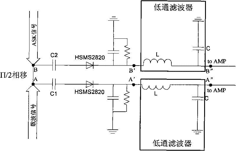
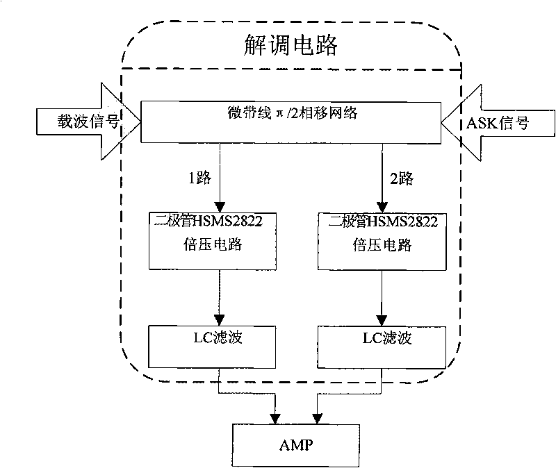
[0013] like figure 2 As shown, the present invention includes a 50 ohm microstrip line, two-way diode mixing circuits and two-way LC low-pass filters. The radio frequency signal will have a phase shift through the microstrip line, and the length of the microstrip line is designed to determine how much the phase shift is. In the present invention, the impedance of the microstrip line is 50Ω, and the input carrier signal and ASK signal generate a phase shift of π / 2 after passing through the microstrip line, and then pass through two-way diode mixing circuits for frequency mixing, and finally pass through two-way LC low After the carrier signal is filtered out by the filter, it is output to the differential amplifier.

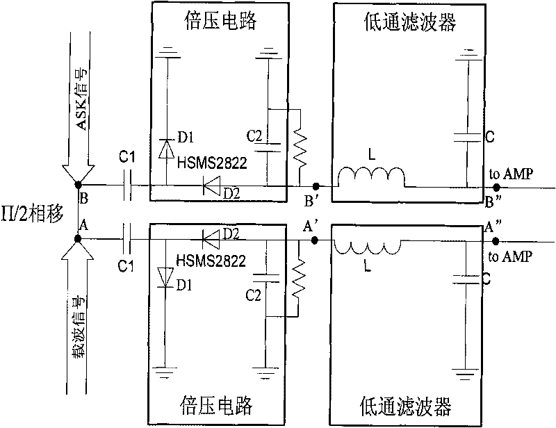
[0014] image 3 It is a circuit diagram of an embodiment of the passive demodulation circuit of the uhf reader of the present invention. In this embo...


PUM


Abstract

The invention relates to a uhf reader, in particular to a uhf reader demodulation circuit, which comprises a 50 ohm microstrip line phase shifting device, a two-way diode mixer circuit and a two-way LC low pass filter; wherein the 50 ohm microstrip line phase shifting device is used for respectively realizing a pi/2 phase shifting on an input carrier signal and an ASK signal; the two-way diode mixer circuit is a voltage-multiplying circuit which is used for mixing the carrier signal and the ASK signal which are subjected to phase shifting by the 50 ohm microstrip line phase shifting device; and the two-way LC low pass filter is used for filtering the carrier signal from a mixing signal and outputting to a difference amplifier. By adopting a simple Schottky diode as a mixing element and designing a mixing circuit into a voltage-multiplying mode to improve receiving sensitivity, the invention simply realizes ASK demodulation and solves the problem of low gain of passive mixing voltage.

Description

technical field [0001] The invention relates to a UHF reader-writer, in particular to a UHF reader-writer demodulation circuit. Background technique [0002] Radio frequency identification (RFID) technology is a non-contact automatic identification technology. Its basic principle is that after the tag enters the magnetic field, it receives the radio frequency signal sent by the reader, and sends out the product information stored in the chip by virtue of the energy obtained by the induced current. Or actively send a signal of a certain frequency; after the reader reads and decodes the information, it sends it to the central information system for relevant data processing. [0003] RFID system generally consists of three parts, namely electronic tags, readers and antennas. The spatial coupling of radio frequency signals is realized between the electronic tag and the reader, and in the coupling channel, energy transmission and data exchange are realized according to the timin...

Claims


Application Information

Patent Timeline
IPC IPC(8): G06K17/00H03D7/02
Inventor 刘胜武长荣江金元杨春华杨国民范旺生
Owner WUHAN WINNINGCHINA MICROSYST TECH
Why Eureka
Try Eureka