Burning tape braider

A technology of taping machine and programmer, applied in static memory, instruments, multiple packages, etc., can solve the problems of increasing the risk of poor contact, prolonged operation time, lengthened IC feet, etc., to achieve cost-effective, convenient and practical , the effect of reducing intermediate operation links and improving production efficiency

Inactive Publication Date: 2010-05-05
叶隆盛
View PDF0 Cites 10 Cited by
  • Summary
  • Abstract
  • Description
  • Claims
  • Application Information

AI Technical Summary

Problems solved by technology

At the same time, the prolongation of the working time will also prolong the time when the IC is exposed to the air, which will cause the oxidation of the IC pin, which will increase the risk of poor contact in the subsequent SMT operation.

Method used


Image

  • Burning tape braider
  • Burning tape braider
  • Burning tape braider

Examples


Embodiment Construction

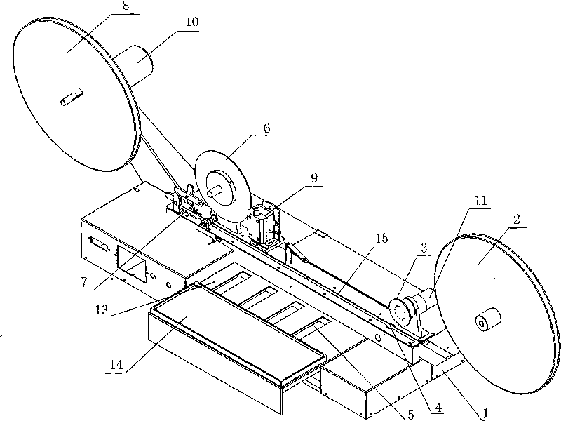
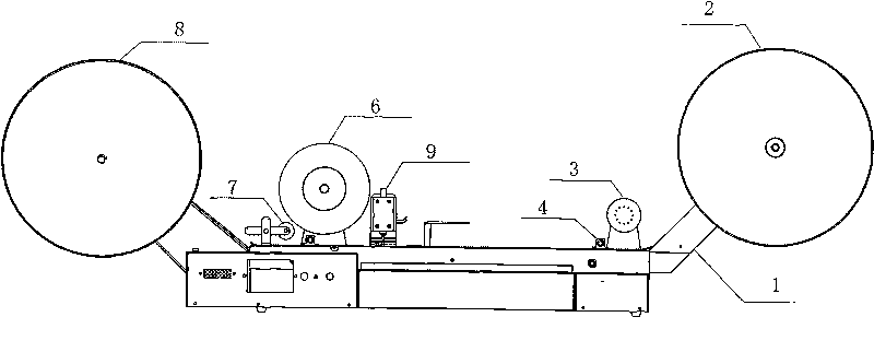
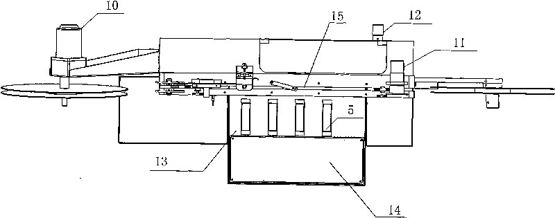
[0016] refer to Figure 1 to Figure 3 , Burn tape machine, comprise support 1, be provided with feed mechanism 2, film closing mechanism 3, carrier tape guide rail 15, film feeding mechanism 6, film pressing mechanism 7 for feeding input in a straight line on described support 1 And the receiving mechanism 8, the side of the support is also provided with a burner 5 for burning IC, and the film receiving mechanism 3 and the receiving mechanism 8 have power sources respectively.

[0017] Further, a film guiding mechanism 4 for guiding is arranged in a straight line between the film winding mechanism 3 and the film feeding mechanism 6 on the support 1 . The film guide mechanism 4 makes the film closing action smoother and enhances the reliability.

[0018] Further, a dotting mechanism 9 is arranged in a straight line between the film winding mechanism 3 and the film feeding mechanism 6 on the support 1 . The dotting mechanism 9 is mainly marked accordingly on the IC.

[0019] ...


PUM


Abstract

The invention discloses a burning tape braider, comprising a bracket, a material-feeding mechanism, a film collecting mechanism, a tape-carrying guide rail, a film delivering mechanism, a film pressing mechanism, a material-collecting mechanism, and a burner; the material-feeding mechanism, the film collecting mechanism, the tape-carrying guide rail, the film delivering mechanism, the film pressing mechanism and the material-collecting mechanism are arranged in a straight line on the bracket, and the burner is arranged on the lateral side of the bracket; and the film collecting mechanism and the material-collecting mechanism are respectively provided with a power source. The burning tape braider integrates burning, spotting and marking, and tape braiding into a whole, has high cost performance and high convenience and practicability; the burning tape braider can realize burning, spotting and tape braiding semi-automatically, thus greatly reducing labor cost and time cost, and effectively improving production efficiency; due to integral assembly line work, intermediate work link is reduced, thus being favorable for improving antistatic protection of IC and anti-oxidation protection of IC pin. The invention can be widely applied or IC processing line as a burning tape braider.

Description

technical field [0001] The invention relates to an IC (chip) braider, in particular to a burner taper combined with a burner function. Background technique [0002] Taping machines currently on the market generally do not have a burning function, and the burning machine does not have a tape making function. At present, the manual TAPE packaging IC burning operation procedure: 1. First use the burning machine to burn the program code into the IC; 2. Then pack the IC into rolls of packaging on the tape machine; 3. Finally, it can go to the patch SMT machine (SMT machine); if dot marking operation is required, dot dot marking must be done after burning and then packaged on the tape machine. Traditionally, these steps are all done manually, and the above-mentioned operating procedure is a waste of manpower and time, and the work efficiency is very low. Steps 1 to 3 of the operating procedure, multiple switching operations will have one more crisis for the IC, such as the threa...

Claims


Application Information

Patent Timeline
Patent Type & Authority Applications(China)
IPC IPC(8): B65B9/04B65B15/04B65B59/00G11C16/10
Inventor 叶隆盛
Owner 叶隆盛
Why Eureka
Try Eureka