Method and device for PLC current-balancing output
An output method and current balancing technology, which is applied in the direction of adjusting electrical variables, control/regulation systems, instruments, etc., can solve problems such as high cost, high cost, and complicated circuits, and achieve low cost, improve work efficiency, and facilitate popularization.
Inactive Publication Date: 2010-04-21
CHENGDU HUAXIA TONGLIAN MICRO CONTROL TECH
View PDF0 Cites 0 Cited by
- Summary
- Abstract
- Description
- Claims
- Application Information
AI Technical Summary
Problems solved by technology
The stability and reliability of the output cannot fully meet the requirements of industrial control, and at the same time, the cost is expensive, and the circuit is complicated and expensive
Method used
View moreImage
Smart ImageViewing Examples
Examples
Embodiment Construction
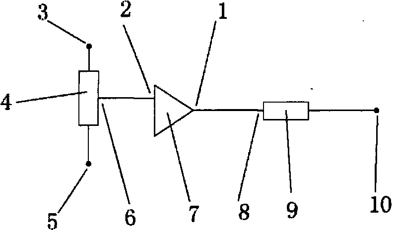
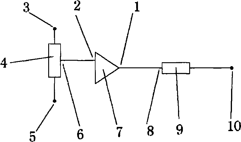
[0010] exist figure 1 Among them, one end of the digital potentiometer 4 is connected to the positive terminal 3 of the power supply, the other end is connected to the negative terminal 5 of the power supply, the output terminal 6 of the digital potentiometer is connected to the input terminal 2 of the operational amplifier, and the output terminal 1 of the operational amplifier is connected to the input terminal 8 of the current sensor.
Login to View More PUM
 Abstract
The invention relates to a method and a device for PLC current-balancing output. The device comprises an operational amplifier output end, an operational amplifier input end, a power supply positive end, a digital potentiometer, a power supply negative end, a digital potentiometer output end, an operational amplifier, a current sensor input end, a current sensor and a current sensor output end, wherein one end of the digital potentiometer is connected with the power supply positive end, and the other end of the digital potentiometer is connected with the power supply negative end; the digital potentiometer output end is connected with the operational amplifier input end; and the operational amplifier output end is connected with the current sensor input end. Through the adjustment of the digital potentiometer, the output of the digital potentiometer is sent to the operational amplifier to change the output current of the operational amplifier; the output current is detected through the current sensor; and the digital potentiometer is adjusted by detection signals so as to achieve the aim of balancing current.
Description
technical field [0001] The invention relates to a balanced current output method and device, in particular to a PLC balanced current output method and device. Background technique [0002] At present, the balanced current output of PLC is completed by analog circuit. The stability and reliability of the output cannot fully meet the requirements of industrial control, and at the same time, the cost is expensive, and the circuit is complicated and expensive. Contents of the invention [0003] The purpose of the invention of a PLC balanced current output method and device is to provide a digitally controlled balanced current output method. To achieve the purpose of complete balanced current output only with digital signals. [0004] By using the PLC balanced current output method and device, people can simply input digital signals to set the magnitude of the current output by the PLC without considering the problem of analog circuits. [0005] In order to achieve the above...
Claims
Login to View More Application Information
Patent Timeline
 IPC IPC(8): G05F1/10
Inventor 罗刚
Owner CHENGDU HUAXIA TONGLIAN MICRO CONTROL TECH
Features
- R&D
- Intellectual Property
- Life Sciences
- Materials
- Tech Scout
- Unparalleled Data Quality
- Higher Quality Content
- 60% Fewer Hallucinations
Learn More Browse by: Latest US Patents, China's latest patents, Technical Efficacy Thesaurus, Application Domain, Technology Topic, Popular Technical Reports.
© 2025 PatSnap. All rights reserved.Legal|Privacy policy|Modern Slavery Act Transparency Statement|Sitemap|About US| Contact US: help@patsnap.com


