
Biplanar friction integral two freedom degree joint

An integrated, double-plane technology, applied in the direction of manipulators, manufacturing tools, joints, etc., can solve the problems of low positioning accuracy, bulky robotic arms, inconvenient operation, etc., achieve high positioning accuracy, good joint rigidity, and improve positioning accuracy and safety effects

Inactive Publication Date: 2011-04-06
昆山市工业技术研究院有限责任公司
View PDF0 Cites 0 Cited by
  • Summary
  • Abstract
  • Description
  • Claims
  • Application Information

AI Technical Summary

Problems solved by technology

[0003] At present, the joint locking methods of medical surgical positioning manipulators are as follows: one is to rely on the servo holding torque output by the motor on each joint, and its disadvantage is that the structure is complicated and the cost is expensive; the other is to install an electromagnetic brake on each joint, and the same There is a disadvantage of complex structure and high cost, and the mechanical arm is relatively heavy; the third is to manually apply force to the wedge-shaped thrust structure of each joint to achieve joint locking
This method is purely passive, with low locking efficiency and inconvenient operation
In addition, in the joint locking mechanism in the prior art, after the joints are locked, there is a gap between the joints, and the gap is not zero, resulting in low positioning accuracy

Method used


Image

  • Biplanar friction integral two freedom degree joint
  • Biplanar friction integral two freedom degree joint
  • Biplanar friction integral two freedom degree joint

Examples


Embodiment Construction

[0022] The present invention will be described in further detail below in conjunction with the accompanying drawings and specific embodiments.

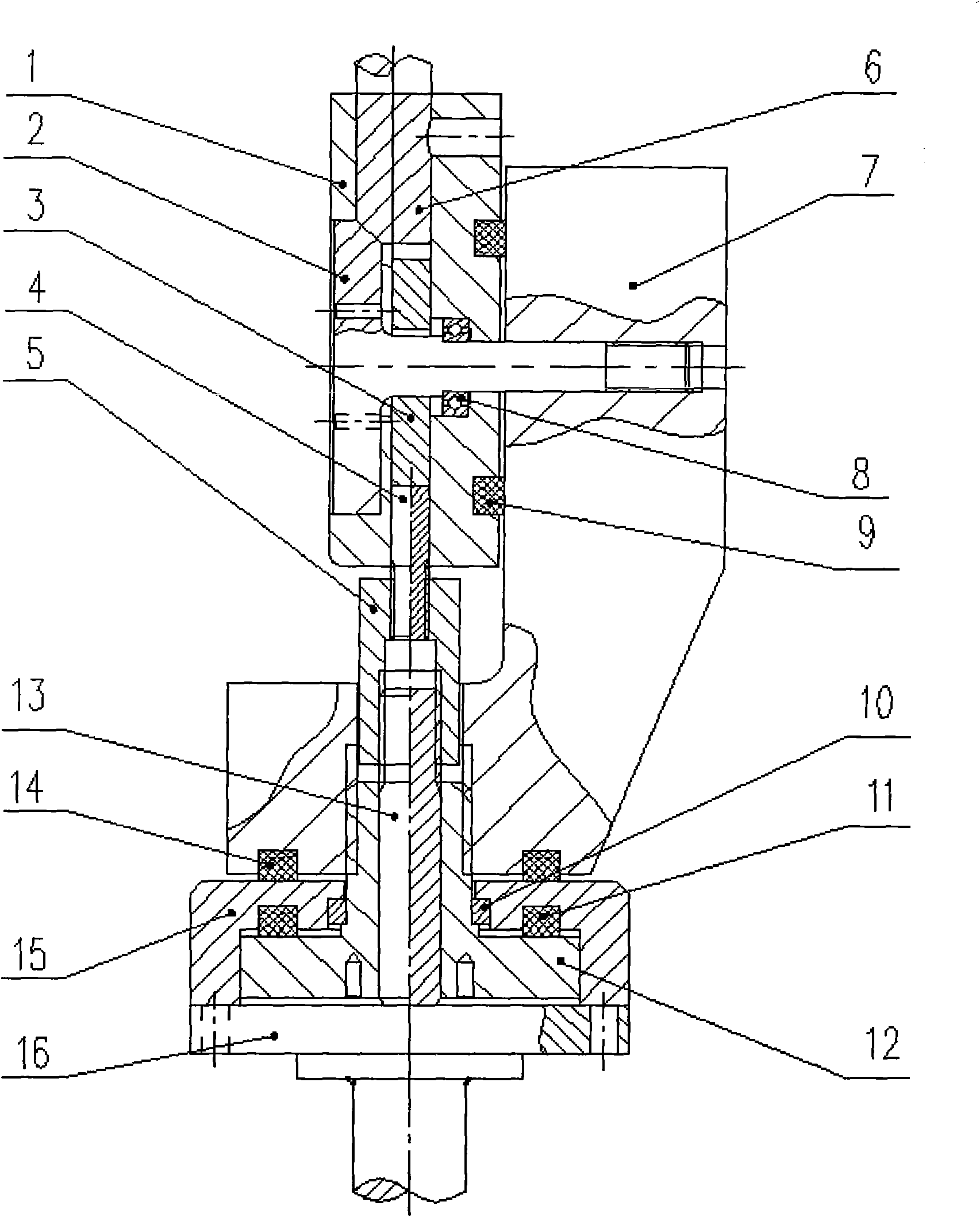
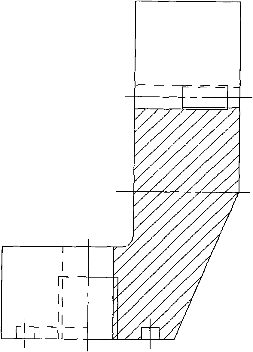
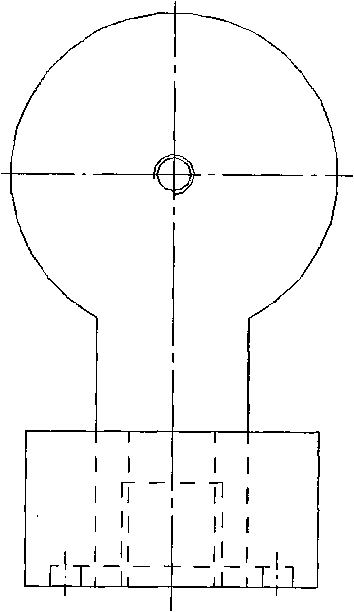
[0023] figure 1 It is a structural schematic diagram of the dual-plane friction integrated 2-DOF joint of the present invention; figure 2 for figure 1 The front view of the joint body in ; image 3 for figure 2 left view of Figure 4 for figure 2 bottom view of Figure 5 for figure 1 The front view of the upper joint T-shaft in ; Image 6 for Figure 5 right view of Figure 7 for figure 1 Front view of the lower joint T-shaft in ; Figure 8 for Figure 7 top view.

[0024] As shown in the figure, the dual-plane friction integrated 2-DOF joint of the present invention includes a joint body 7, a lower joint T-shaped shaft 12 and an upper joint T-shaped shaft 2, wherein the joint body 7 is in an "L" shape, and the upper The upper outer edge of the lower plane of the joint T-shaped shaft 2 is chamfered to form a wedge-sha...


PUM


Abstract

The invention relates to a biplanar friction integral two degree of freedom joint. A wedge surface is arranged on the outer edge of the upper side of a lower plane of an upper joint T-shaped shaft, an upper joint force-transfer sliding block is sleeved on a rod part, wherein the diameter of a round hole of the upper joint force-transfer sliding block is more than the diameter of a rod part; the rod part is arranged in an upper joint casing through a bearing and extends out of the upper joint casing to be threaded with one end of a joint platform body, a wedge surface at the end part of a pushrod is matched with the wedge surface of the upper joint T-shaped shaft; a lower joint T-shaped shaft is connected to the lower part of the other end of the joint platform body through an external thread and is arranged in a lower joint close cover through a bearing, the lower joint close cover is fixedly connected with a joint supporting shaft; and an ejector rod is arranged in a hollow structure of the lower joint T-shaped shaft, the lower end of the ejector rod is contacted with the upper end face of the joint supporting shaft and the upper end is contacted with the upper joint force-transfer sliding block. The invention has the characteristics of small size, compact structure, light weight, large locking torque, simple structure, zero locked joint clearance, long service life and the like, and can be suitable for the joint locking of various small mechanical arms.

Description

technical field [0001] The invention relates to a rotary joint, in particular to a dual-plane friction integrated 2-degree-of-freedom joint, belonging to an underactuated mechanical arm joint locking mechanism. Background technique [0002] Since the 1990s, with the rapid development of intelligent robot technology, computer technology, and medical surgery technology, service robots, such as minimally invasive surgical robot technology, have become one of the international frontier research hotspots that domestic and foreign scholars and related institutions have paid attention to. . This is a new multidisciplinary technical field, and its development is considered as a symbolic progress in surgical treatment. [0003] At present, the joint locking methods of medical surgical positioning manipulators are as follows: one is to rely on the servo holding torque output by the motor on each joint, and its disadvantage is that the structure is complicated and the cost is expensiv...

Claims


Application Information

Patent Timeline
Patent Type & Authority Patents(China)
IPC IPC(8): B25J17/00
Inventor 唐粲程胜张建伟
Owner 昆山市工业技术研究院有限责任公司
Learn More