
Massaging machine

A massage body and drive mechanism technology, applied in vibration massage, kneading massage equipment, massage auxiliary products, etc., can solve the problems of large-scale massage machines and complex structures

Active Publication Date: 2013-03-06
PANASONIC CORP
View PDF1 Cites 19 Cited by
  • Summary
  • Abstract
  • Description
  • Claims
  • Application Information

AI Technical Summary

Problems solved by technology

Therefore, the massaging machine is enlarged and the structure is complicated

Method used


Image

  • Massaging machine
  • Massaging machine
  • Massaging machine

Examples


Embodiment Construction

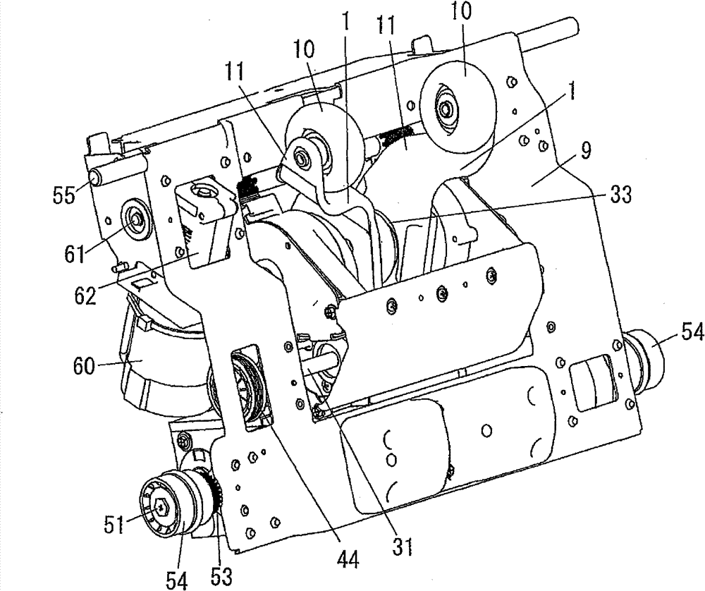
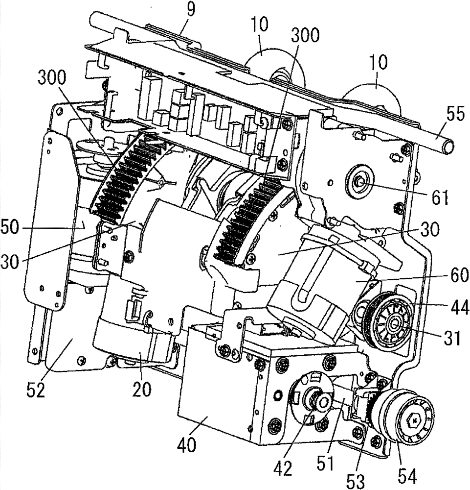
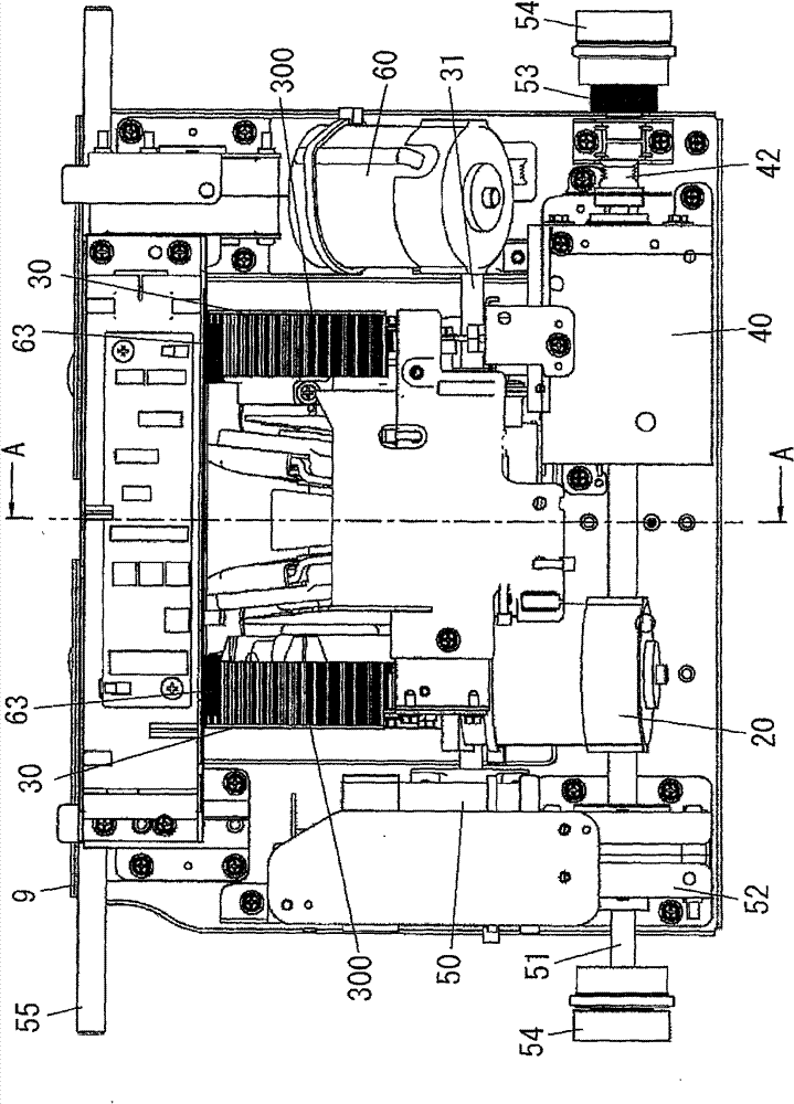
[0016] Hereinafter, a massage machine according to one embodiment of the present invention will be described. The mechanism unit of the massage machine is shown in the figure. The mechanism unit is designed to be arranged in the backrest of the chair and to automatically move upwards and downwards in the backrest. This mechanism unit includes a frame 9 having an opening at the center of the front surface, a vertical travel shaft 55 , a vertical drive shaft 51 , and a strength adjustment drive shaft 61 . The vertical travel shaft 55 , the vertical drive shaft 51 , and the strength adjustment drive shaft 61 are respectively installed between the left side plate portion and the right side plate portion of the frame 9 . The treatment mechanism block is arranged between the left and right side plate portions of the frame 9 .

[0017] The motor 50 for driving up and down is fixed to a side plate portion (for example, a left side plate portion) of one side of the frame 9 . The ver...


PUM


Abstract

A massaging machine comprises a curing mechanism block, wherein the curing mechanism block comprises a kneading drive mechanism (20, 32, 33) for causing a curing mechanism (10) to execute the kneadingmassaging action, and a beating drive mechanism (42, 43, 44, 45) for causing the curing mechanism (10) to execute beating massaging action; a strength adjustment mechanism (61) for causing the curingmechanism block to rotate by taking a shaft (31) as the center and changing the position of the curing mechanism (10) to massaged part (back), and adjusting the strength of the massaging action. Thebeating drive mechanism (42, 43, 44, 45) rotates and drives along the shaft through the shaft (31) as the rotating center of the curing mechanism block such that the curing mechanism (10) executes thebeating massaging action.

Description

technical field [0001] The invention relates to a massage machine with the function of rubbing and massage, the function of adjusting the intensity of rubbing and massage, and the function of percussion massage. Background technique [0002] For example, Patent Document 1 discloses a massage machine built in a chair back or the like, which rubs and massages the back of a human body. In this massage machine, the intensity of rubbing massage is adjusted by changing the position of the treatment member for massage forward or backward relative to the back of the human body. [0003] In the massage machine of Patent Document 1, the treatment member is driven to perform both rubbing massage and percussion massage. Therefore, in the massage machine of patent document 1, the treatment member block provided with both the drive mechanism for a rubbing massage operation, and the drive mechanism for a percussion massage operation is provided. The intensity of the massage can be adjust...

Claims


Application Information

Patent Timeline
Patent Type & Authority Patents(China)
IPC IPC(8): A61H23/02A61H7/00
Inventor 仓田阳介多贺谷兼介中村润二大轮昌俊
Owner PANASONIC CORP
Learn More