Switching device

A switchgear and equipment technology, applied in the protection switch, protection switch parts, protection switch terminal/connection, etc., can solve the problems of unspecific and unsuitable load current loop current feedback, etc., to achieve flexible use, reasonable installation and The effect of space cost

Active Publication Date: 2010-03-24
ELLENBERGER POENSGEN
View PDF0 Cites 3 Cited by
  • Summary
  • Abstract
  • Description
  • Claims
  • Application Information

AI Technical Summary

Problems solved by technology

Although switching devices usually have additional signal terminals at which information about the switching state of the switching device can be drawn out, these signal terminals are usually designed for currents with less power and are neither specific nor suitable for based on current feedback from the load current loop

Method used


Image

  • Switching device
  • Switching device
  • Switching device

Examples


Embodiment Construction

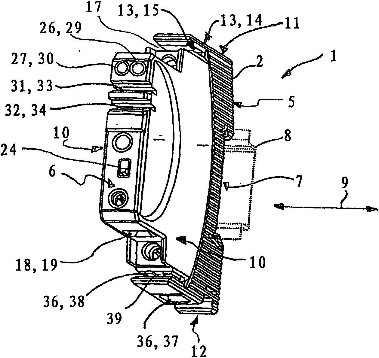
[0024] exist figure 1 The switching device 1 shown first in view from the outside comprises a housing 2 made of insulating material. The switching device 1 is designed as a series-assembled device and has a typical, stepped housing shape for such devices, with a housing head 3 and an opposite housing base 4 elongated on both sides. The housing base 4 here forms the housing segment that adjoins the housing rear 5 , while the housing head 3 forms the housing segment that adjoins the housing front 6 .

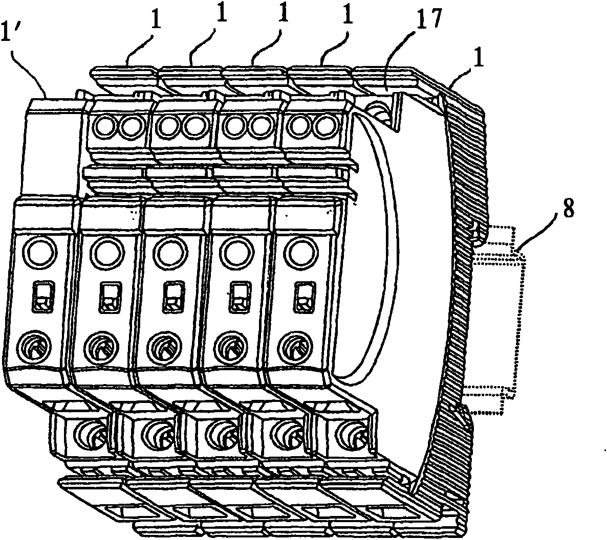
[0025] The switchgear 1 is designed for a defined assembled state in which the housing rear 5 of the housing 2 faces towards the rear panel of the switch cabinet, while the housing front 6 faces in the assembled position when viewed towards the switch cabinet. operator. For installation, the switching device 1 has a peg 7 on the housing rear 5 , with which the switching device 1 can be snapped onto a support rail 8 (shown dotted in the figure).

[0026] The central axis of the ...


PUM


Abstract

The invention relates to an electrical switching device (1) that allows for a rational and simple structure of an electrical system, particularly a power distribution system. The switching device (1), particularly embodied in the form of a serial installation device, comprises a housing (2) and a switching unit (20) accommodated therein for interrupting an electrical circuit, a feed connection (13) for supplying a current to the switching unit (20), said feed connection having a first coupling contact (15) for contacting a current busbar (16), a load connection (18) for contacting a supply line (18c) of a load circuit (18b) with the switching unit (20), and a return connection (36) having a terminal clamp (37) for contacting the return line (36a) of the load circuit (18b) and a second coupling contact (38) connected to the terminal clamp (37) inside the housing for contacting a second current busbar (40).

Description

technical field [0001] The invention relates to an electrical switching device, in particular in the form of a series assembled device. Background technique [0002] Electrical switching devices such as protective switches, mechanical switches, electronic switches or mechatronic switches or relays usually have feed-in terminals, via which the current conductors on the grid side can be connected and thus lead in current, and load terminals, via which The load terminal can be connected to the current conductor of the output on the load side. [0003] In the following, an electrical distribution system generally refers to an electrical installation having multiple electrical load (current) circuits fed with current from a common main current conductor and which are connected to a common feedback current arrangement. In the context of such power distribution systems, switching devices are usually arranged, in particular, at branch points at which the load current circuits are s...

Claims


Application Information

Patent Timeline
IPC IPC(8): H01H71/08
CPCH01H71/082H01R9/2675H01H71/08
Inventor H·罗斯
Owner ELLENBERGER POENSGEN
Why Eureka
Try Eureka