
Pusher for movable furniture elements

A technology for pushing out devices and furniture parts, which is applied to switches with brake parts, wing parts, door/window accessories, etc.

Active Publication Date: 2010-03-24
HETTICH ONI
View PDF9 Cites 13 Cited by
  • Summary
  • Abstract
  • Description
  • Claims
  • Application Information

AI Technical Summary

Problems solved by technology

However, the known solution is not very suitable for practical use, because it requires a large construction space and greatly impairs the appearance of the furniture on which it is installed

Method used


Image

  • Pusher for movable furniture elements
  • Pusher for movable furniture elements
  • Pusher for movable furniture elements

Examples


Embodiment Construction

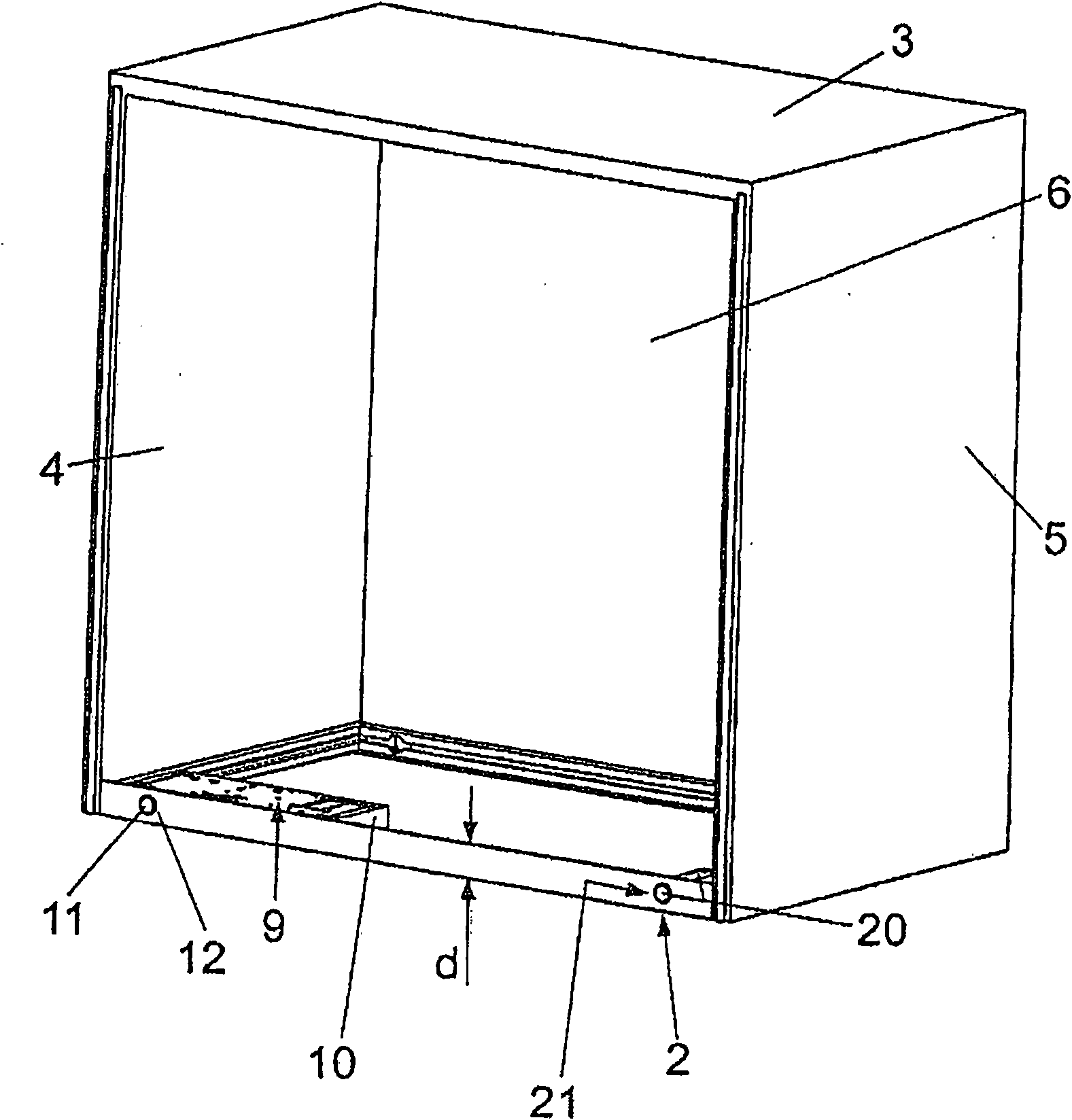
[0022] figure 1 Shows a perspective view of an exemplary box-shaped furniture body 1 comprising a plurality of walls, here exemplary comprising a bottom wall 2 serving as a base, an upper or top wall 3, two side walls 4, 5 and a rear wall6.

[0023] The walls 2-6 are preferably positioned at right angles to each other, wherein the bottom wall 2 and the top wall 3 are generally horizontal, while the side walls 4, 5 and the rear wall 6 are vertically positioned.

[0024] The furniture body that opens to one side like this can use movable furniture parts, revolving door 7 (it is shown in Figure 4 Middle) closed, it can be on at least one or more single-axis or multi-axis hinges 8 ( Figure 4 can be partly seen in ) rotate about a generally vertically positioned fixed or spatially movable (however theoretically existing) axis of rotation D and thus open and close.

[0025] The hinge 8 itself can constitute almost any. A damped hinge is preferably used and preferably prevents ...


PUM


Abstract

A pusher for a movable furniture element, in particular a revolving door, a piece of furniture having a body (1) with at least one wall (2) or a plurality of walls (2-6), is characterised in that thepusher is designed in such a way that it can be integrated into one of the walls (2-6) of the piece of furniture.

Description

technical field [0001] The invention relates to an ejection device according to the preamble of claim 1 for movable furniture parts, in particular pivotable doors, and to a piece of furniture with such an ejection device. Background technique [0002] DE 202004007168U1 discloses a known type of ejection device. DE 20308218 U1 discloses a closing and damping device for movable furniture parts. DE 202005020872 U1 likewise discloses a damper for a movable furniture part. [0003] Electric ejection devices for swing doors on furniture are thus known per se. However, the known solution is not very suitable for practical use, since it requires a relatively large installation space and significantly impairs the appearance of the furniture on which it is installed. Contents of the invention [0004] The solution of this problem is the first object of the present invention. [0005] The invention achieves this object by the subject-matter of claim 1 . Furthermore, the inventio...

Claims


Application Information

Patent Timeline
Patent Type & Authority Applications(China)
IPC IPC(8): E05F15/12E05F1/10E05F5/02
CPCE05F1/105E05Y2800/232E05Y2900/20E05Y2201/426E05Y2201/434E05Y2600/41E05F5/02E05Y2800/174E05F15/12E05Y2201/726E05F15/611
Inventor O·舍尔U·索博勒夫斯基S·安德舒斯A·戈格斯T·尼迪克
Owner HETTICH ONI
Learn More