Eureka AIR delivers breakthrough ideas for toughest innovation challenges, trusted by R&D personnel around the world.

Dual clutch arrangement having a piston guide element

A technology of clutches and friction clutches, applied in the field of clutch systems, which can solve the problems of large inertia of external plate brackets and large structural space

Active Publication Date: 2010-03-17
BORGWARNER INC
View PDF1 Cites 9 Cited by
  • Summary
  • Abstract
  • Description
  • Claims
  • Application Information

AI Technical Summary

Problems solved by technology

Not only does this require a large installation space in the axial direction of the clutch, but the moment of inertia of the rotating outer plate carrier is also particularly high, which has a negative effect on the dynamic behavior of the transmission.

Method used


Image

  • Dual clutch arrangement having a piston guide element
  • Dual clutch arrangement having a piston guide element
  • Dual clutch arrangement having a piston guide element

Examples


Embodiment Construction

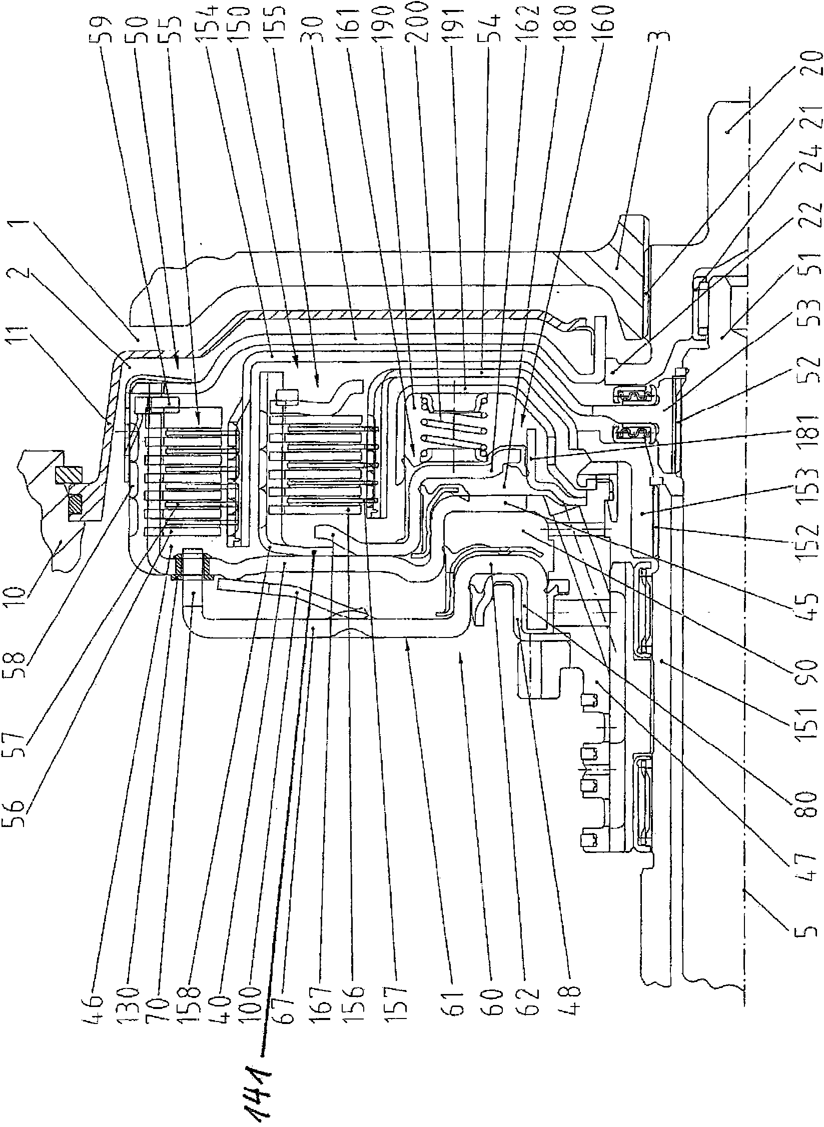
[0024] figure 1 A double shaft clutch with two oil-lubricated friction clutches 50, 150 is shown. This non-positive shifting clutch has two sets of plate packs 55 , 155 arranged radially in sequence. The first plate set 55 is arranged on a larger radius than the second plate set 155 . The two clutches 50, 150 are hydraulically connected. The disengagement of the respective clutches 50 , 150 takes place via spring elements and / or hydraulically via the corresponding cylinder-piston unit. The spring elements 100, 200 are, for example, mechanical springs, such as coil springs and / or diaphragm springs. Such clutch systems are commonly used in passenger cars.

[0025] The clutch system is located, for example, between the multi-shaft transmission of the vehicle and the engine. The engine is usually a gasoline engine or a diesel engine. A single-mass or dual-mass clutch 3 (Ein-oder Zweimassenkupplung) is often installed between the engine and the clutch system.

[0026] Due to...


PUM


Abstract

The invention relates to a clutch system for motor vehicle drives having a clutch input shaft (20) and at least one transmission input shaft (51,151), wherein the transmission input shaft is connectedto the clutch input shaft via a fluid-lubricated and cooled friction clutch (50, 150) equipped with slat packs (55, 155), which is positioned in the transmission space, and wherein at least one slatpack is pressed against a stop (59) for coupling via a force transmission element (62) that can be moved by an actuating member (60, 160). At least one coupling component of the friction clutch has aplurality of recesses (49) in the region of the corresponding slat pack. The force transmission section of the corresponding actuating member further comprises a plurality of fingers (70) that act upon the corresponding slat pack through the recesses. The present invention creates a clutch system comprising an exterior slat carrier having a short construction size in the axial direction with at least one clutch.

Description

technical field [0001] The invention relates to a clutch system for driving a motor vehicle, the system having a clutch input shaft and at least one transmission input shaft, wherein the transmission input shaft is connected to the clutch input shaft via a friction clutch, the friction clutch is mounted in the area of ​​the transmission and is equipped with plate packs; and wherein, for connection, at least one plate pack is pressed against a stop by a force transmission part drivable by the actuating member. Background technique [0002] EP 0 758 434 B1 discloses such a clutch system. This system shows a multi-plate clutch with multiple outer plate carriers, each of which is more than twice as wide in the axial direction as the width of the plate pack it houses. Not only does this require a large installation space in the axial direction of the clutch, but the moment of inertia of the rotating outer plate carrier is also particularly high, which has a negative effect on th...

Claims


Application Information

Patent Timeline
IPC IPC(8): F16D25/0638F16D25/10
CPCF16D2021/0661F16D25/0638F16D21/06F16D25/10F16D25/12
Inventor R·格拉泽沃尔G·尼克拉斯H·J·豪科
Owner BORGWARNER INC
Why Eureka
Eureka Blog
Learn More