LED display system

A display system and LED module technology, which is applied to static indicators, instruments, identification devices, etc., can solve the problems of many components, affecting the visual range, and insufficient transparency of the display screen

Inactive Publication Date: 2010-03-17
BEIJING JUSHU DIGITAL TECH DEV
View PDF0 Cites 2 Cited by
  • Summary
  • Abstract
  • Description
  • Claims
  • Application Information

AI Technical Summary

Problems solved by technology

Since the luminous pixels of the display screen are all set on an opaque planar structure, the application of the display screen in some occasions is limited or cannot play a better effect
For example, installing a large-area conventional LED display outside or inside the glass curtain wall of a building will seriously affect the lighting inside the building and the visual range of people in the building, or affect the visual range viewed from the outside of the building. The screen has the characteristics of many components, many connections, many power supplies, complex circuits, and many components. It is difficult to guarantee that there will be no problems in use, poor selectivity, and low stability.
[0004] Alternatively, there are also LED displays in which the LED display is set to be transparent, which greatly improves the transparency and heat dissipation of the opaque flat plate structure, but the distance between each pixel of the LED display is still set according to the traditional method. The transparency of the display screen is still not high enough, it still affects part of the visual range of people in the building, and it is difficult to withstand huge temperature differences and strong winds

Method used


Image

  • LED display system
  • LED display system
  • LED display system

Examples


Embodiment 1

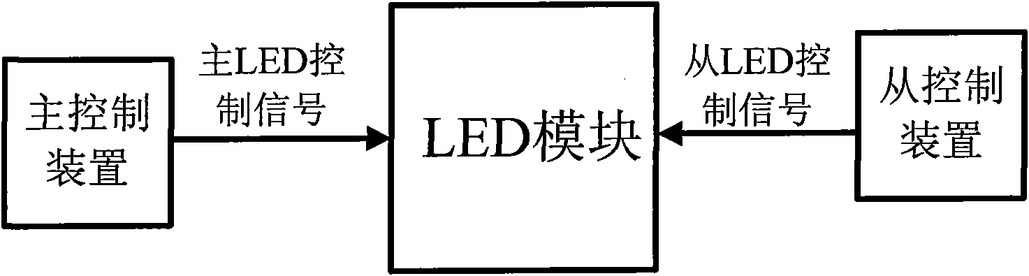
[0024] Such as figure 1 As shown, this embodiment provides an LED display system, and the LED system includes one or more LED modules, a master control device and one or more slave control devices.

[0025] For example, the LED module includes two or more installation strips, several LED lighting units and their control modules, power lines, one or more main signal lines and one or more slave signal lines. Wherein, each LED light-emitting unit is installed and fixed on each installation bar, and each LED light-emitting unit can be arranged in a dot matrix, thereby forming an LED module, and one or more LED modules can form LED displays of different shapes and sizes. , Each LED display can be used to display various video information.

[0026] The power supply line may include one or more power supply positive lines and one or more power supply negative lines, and each power supply positive line is connected to the power supply for transmitting electric energy and providing vo...

Embodiment 2

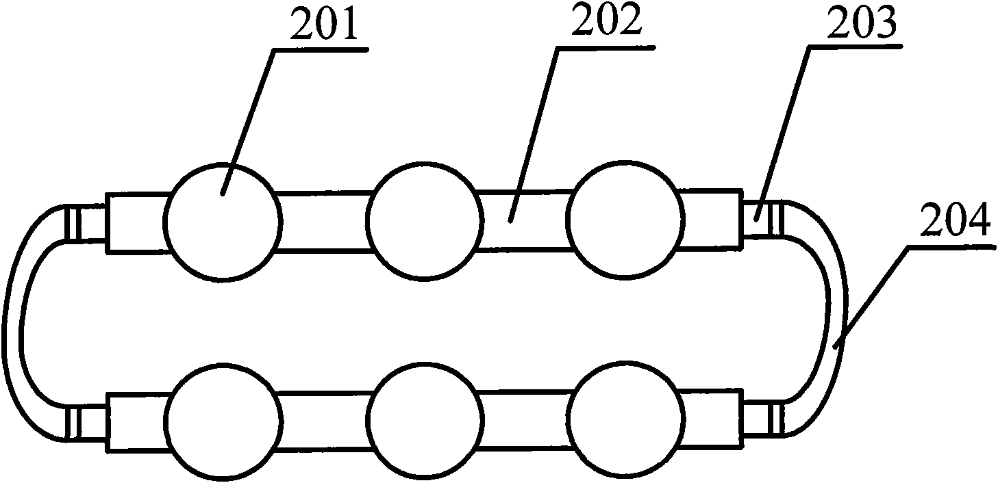
[0046] like figure 2 As shown, on the basis of the above examples, several LED light emitting units 201 are installed on each installation bar, and the end of any installation bar 202 is provided with a connecting part 203, wherein the connecting part 203 can be arranged on the installation Any one end of the strip 202 is disposed, and may also be disposed at both ends of the installation strip 202, and the connecting portion 203 is used for connection between the two installation strips. For example, the connection part 203 includes a power line connection part, a main signal line connection part and a slave signal line connection part, wherein the power line connection part may include a power supply positive pole connection part and a power supply negative pole line connection part, which are used to connect with adjacent installation strips respectively. The power supply positive line and the power supply negative line on the corresponding electrical connection, the main ...

Embodiment 3

[0051] On the basis of the above examples, in the control module of each LED lighting unit, the fault detection sub-module is also connected to a fault data output line for outputting fault data. For example, a fault data output line is also set in an LED module, the fault data output line is connected to the fault detection sub-module, and the fault data output line is used to output fault data, that is, when the main LED control When the signal is correct or incorrect, the fault data line correspondingly outputs the fault data that the main signal line is normal or fails. For example, one end of the fault data output line can be connected with the control system, and directly Display fault data, that is, through the output fault data, you can know whether each line has a fault, and quickly find the location of the fault, making maintenance simple and convenient.

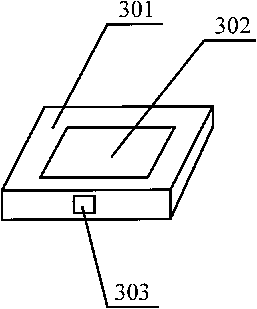
[0052] like image 3 As shown, on the control device 301, there is also a status display module 302, the status...


PUM


Abstract

The invention discloses an LED display system which comprises an LED module, a master control device and a slave control device, wherein the LED module comprises at least two mounting bars, a plurality of LED luminous units, a control module of the LED luminous units, a power line, at least one master signal wire and at least one slave signal wire; the master control device is connected with the master signal wire and used for generating a master control signal; the slave control device is connected with the slave signal wire and used for generating a slave control signal; the control module is provided with a plurality of function modules which are used for detecting whether the master control signal is right, judging whether the master signal wire has fault, insulating the master controlsignal, replacing the master control signal by the slave control signal as well as driving and controlling the LED luminous units; and distance among the LED luminous units is set to be at least 5 cm, and an LED light-emitting diode with the same separation grade and adjacent separation grades thereof can be adopted. The LED display system has high transparency, good heat dissipation effect, strong wind resistance, convenient and flexible assembly and disassembly, better selectivity and high stability.

Description

technical field [0001] The present invention relates to an LED illuminating device, in particular to an LED display system. Background technique [0002] LED has been widely valued for its high luminous efficiency, long service life, safety, reliability, environmental protection and energy saving. As an important means of information dissemination, LED display has become a symbol of urban information modernization. With the continuous progress of social economy and the continuous improvement of LED display technology, people's understanding of LED display will become more and more in-depth. , and its application fields will become wider and wider. [0003] In the prior art, the LED display screen is generally on an opaque flat plate structure, and a pixel is composed of light-emitting diodes or LEDs, and each pixel is arranged in a matrix at a certain interval to form a unit board with patterns and text information, which is controlled by a control device. , so as to displ...

Claims


Application Information

Patent Timeline
Patent Type & Authority Applications(China)
IPC IPC(8): G09F9/33G09G3/14G09G3/32
Inventor 商松
Owner BEIJING JUSHU DIGITAL TECH DEV
Why Eureka
Try Eureka