
Method for reducing handover delay in long term evolution systems

A long-term evolution and time-delay technology, applied in the communication field, can solve the problems of increasing handover delay, failure of wireless link recovery, and failure to store UE context, etc.

Inactive Publication Date: 2010-03-10
POTEVIO INFORMATION TECH
View PDF0 Cites 40 Cited by
  • Summary
  • Abstract
  • Description
  • Claims
  • Application Information

AI Technical Summary

Problems solved by technology

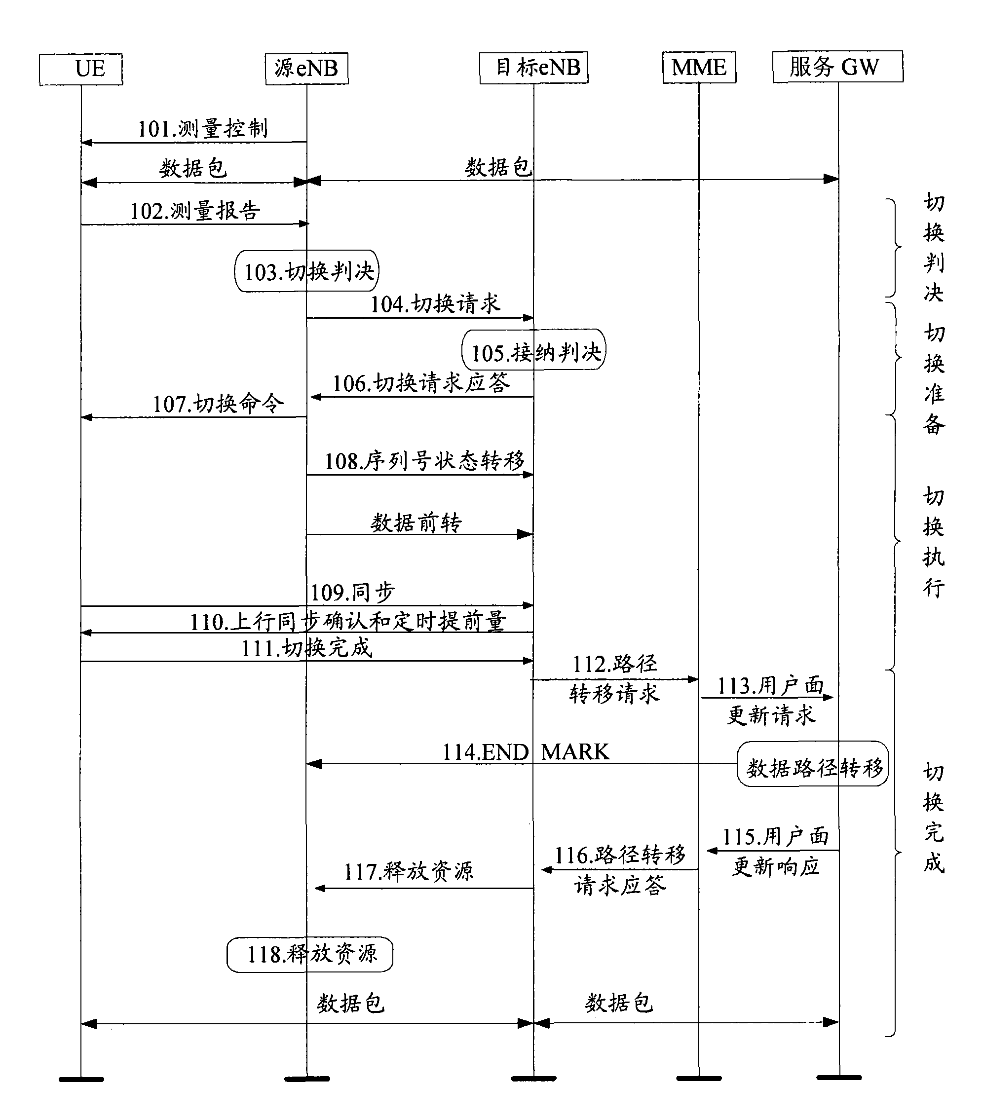
[0043] It can be seen from the above scheme that during the handover preparation process, the source eNB selects the optimal target cell from the candidate target cells that meet the handover decision conditions, and only sends a Handover Request message to the candidate target eNB that manages the optimal target cell, triggering the standby target cell. The selected target eNB reserves resources for the current handover. Once the optimal target cell does not agree to perform handover, since the alternative target eNB that manages other cells that meet the handover conditions other than the optimal target cell does not reserve resources for the handover Therefore, the source eNB needs to re-initiate the handover preparation process, that is, it needs to re-select another cell that meets the judgment conditions as the new target cell, and submit the new target cell to the candidate for managing the new target cell. The target eNB sends a Handover Request message, and performs related operations according to the Handover Request ACK message or Handover Preparation Failure message returned by the eNB, which will inevitably increase the handover delay
[0044] However, when a radio link failure occurs between the UE and the serving cell of the serving cell, the source eNB only sends a Handover Request message to the target eNB that manages the optimal target cell to trigger the target eNB to prepare for handover. The context of the UE is stored in the eNB and the optimal target eNB. If the UE selects a cell managed by an eNB other than the source eNB and the optimal target eNB when performing radio link recovery, the radio link Recovery cannot be performed normally, the UE may need to enter the RRC_IDLE state first, which will increase the delay in switching

Method used


Image

  • Method for reducing handover delay in long term evolution systems
  • Method for reducing handover delay in long term evolution systems
  • Method for reducing handover delay in long term evolution systems

Examples


Embodiment Construction

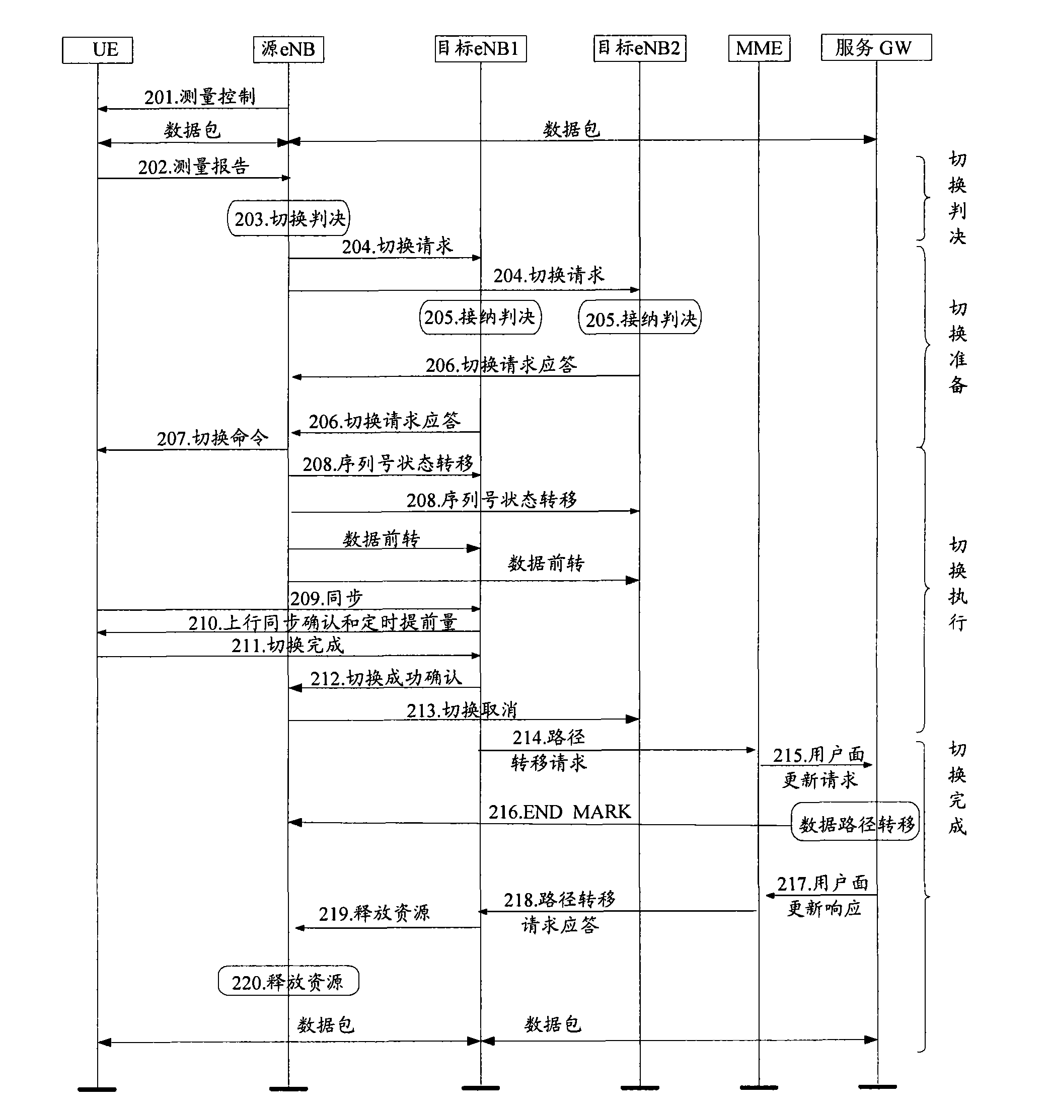
[0054] The core idea of ​​the present invention is that the source base station eNB sends a handover request to all candidate target eNBs managing the candidate target cells that meet the handover decision conditions; if any of the candidate target cells managed by the candidate target eNB agrees to If the handover request is received, the candidate target eNB reserves resources for the current handover, stores the context of the user equipment UE performing the current handover, and notifies the source of the candidate target cell that agrees to the handover request eNB.

[0055] In order to make the object, technical solution and advantages of the present invention clearer, the present invention will be further described in detail below with reference to the accompanying drawings and examples.

[0056] figure 2 It is a flow chart of a method for handover in an LTE system provided by an embodiment of the present invention, such as figure 2 As stated, the method includes: ...


PUM


Abstract

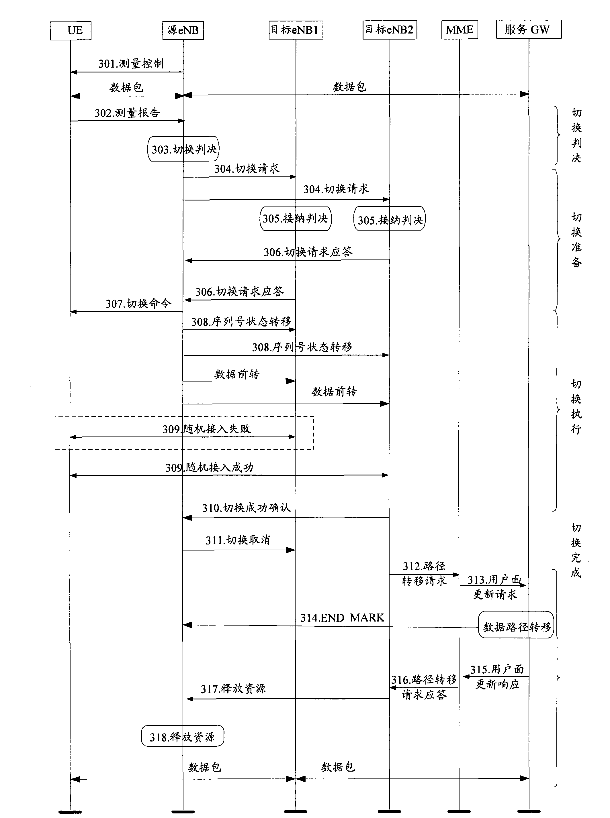
The embodiment of the invention discloses a method for reducing handover delay in LTE systems. The method comprises that: source eNB sends a handover request to alternative target eNB of all alternative target cells of which the management meets handover judgment conditions, agrees to allow the alternative target eNB to which the alternative target cells with the handover request to reserve resources for current handover, and stores context of user equipment UE performing the current handover; and the alternative target eNB informs the source eNB of the information of the alternative target cells agreeing to the handover request. The method can trigger all alternative target eNB to be reserved resources for the current handover so as to reduce the handover delay caused by a currently selected target eNB not agreeing to hand over. In addition, in the process of handover execution, the source eNB simultaneously forwards data to all the alternative target eNB returning response to the handover request, so data loss caused by handover failure can be avoided.

Description

technical field [0001] The present invention relates to handover technology in the communication field, in particular to a method for shortening handover time delay in a Long Term Evolution (Long Term Evolution, LTE) system. Background technique [0002] The handover process in the LTE system includes a handover decision phase, a handover preparation phase, a handover execution phase and a handover completion phase. In the following, the method for performing handover in the LTE system will be introduced in combination with the current specific process of handover in the LTE system. [0003] figure 1 It is a flowchart of a method for switching in an LTE system at present, such as figure 1 As shown, the method includes: [0004] Step 101 , a source base station (eNB) controls a user equipment (User Equipment, UE) to measure the communication quality between the UE and each neighboring cell, and forms a measurement report. [0005] Steps 102 to 103 are the handover decisio...

Claims


Application Information

Patent Timeline
IPC IPC(8): H04W36/08H04B7/26
Inventor 高兴航伍振兴
Owner POTEVIO INFORMATION TECH
Learn More