
Rotary power tool operable in either an impact mode or a drill mode

A technology of rotating power and power tools, which is applied in the field of impact drivers, can solve problems such as heavy and bulky, and achieve the effect of low cost and cost saving

Inactive Publication Date: 2010-03-03
ROBERT BOSCH GMBH
View PDF2 Cites 9 Cited by
  • Summary
  • Abstract
  • Description
  • Claims
  • Application Information

AI Technical Summary

Problems solved by technology

A disadvantage of existing hybrid designs is that they are bulky and / or heavy since the housing must accommodate the implements used to achieve all modes

Method used


Image

  • Rotary power tool operable in either an impact mode or a drill mode
  • Rotary power tool operable in either an impact mode or a drill mode
  • Rotary power tool operable in either an impact mode or a drill mode

Examples


Embodiment Construction

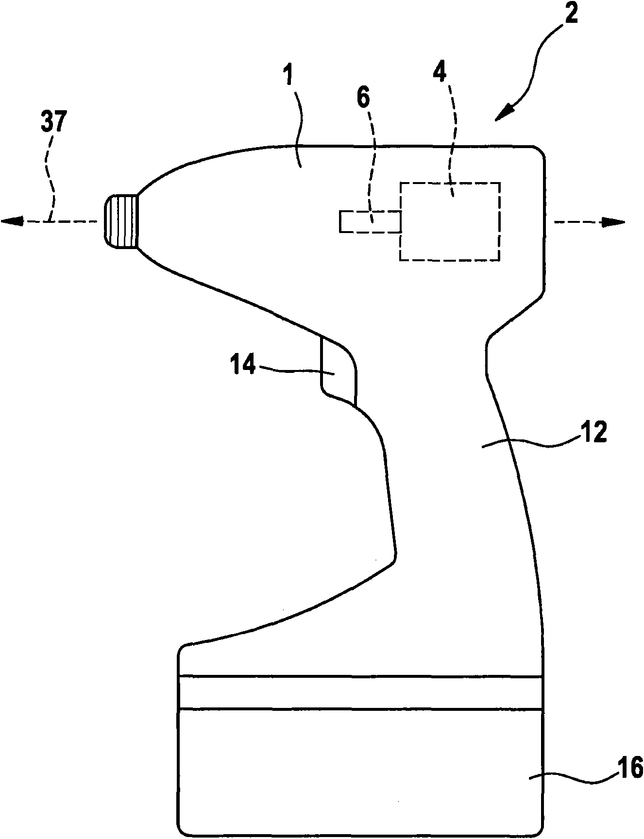
[0022] figure 1 An example of a rotary tool according to the invention is shown. A motor 4 and an associated motor shaft 6 are arranged within the housing 1 of the impact driver 2 . The rotation of the motor shaft 6 is converted through various reduction planetary gears in the gearbox 8 to rotate the drive shaft 10 . The tool is provided with a handle 12 and a trigger 14 so that the user can conveniently operate the tool. A battery 16 provides DC power, but AC power is also a standard alternative.

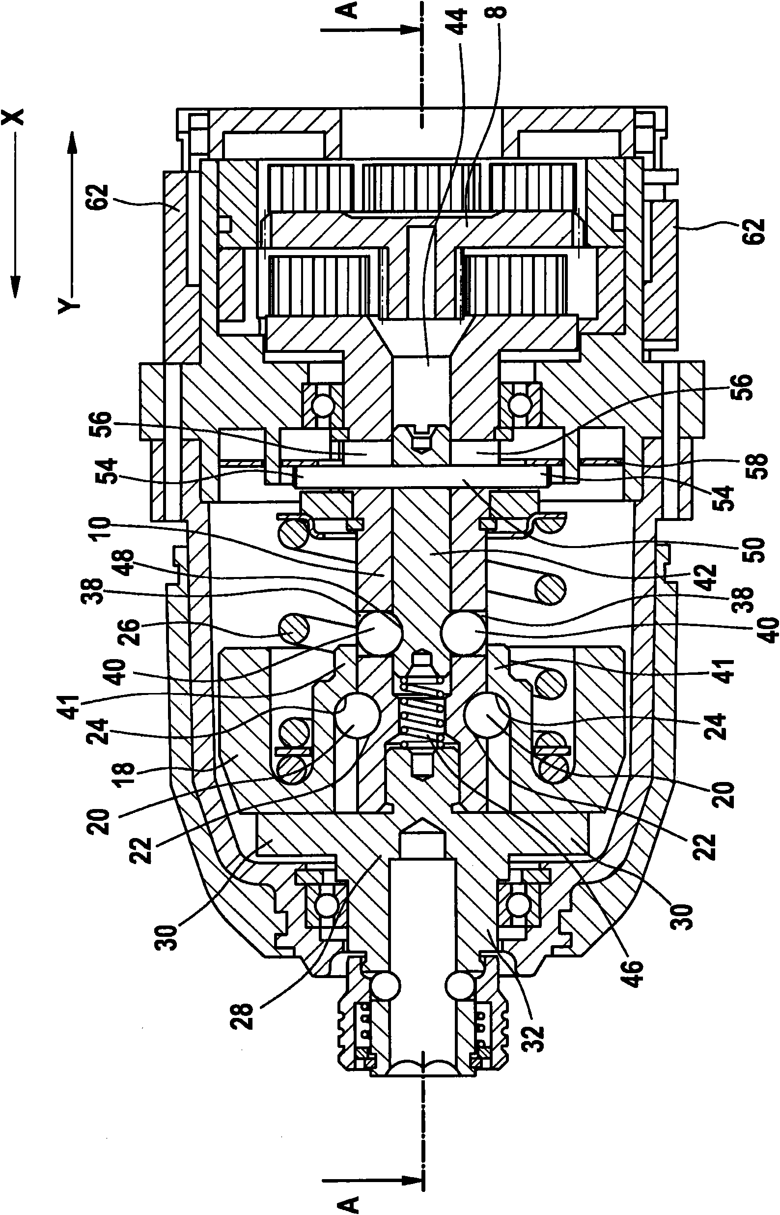
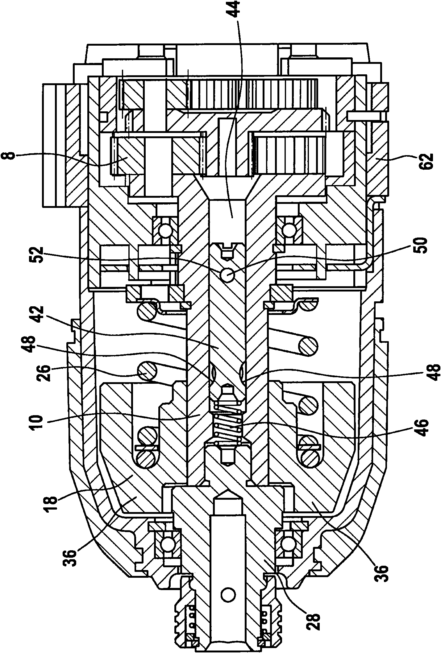
[0023] The impact driver 2 can operate in at least two different modes, an impact mode and a drilling mode, although it can operate in many more modes. In impact mode, the tool operates like a regular impact driver, delivering intermittent impacts to the output shaft when high torque is required. As will be described below, in drill mode the impact function is turned off and the tool operates more like a standard drill / driver. A comparable impact driver 2 representing a prefer...


PUM


Abstract

A rotary power tool operable in either an impact mode or a drill mode comprising a driveshaft (10), an output shaft (32), a hammer (18) coupled to the driveshaft (10) for transmitting torque to the output shaft (32), and a blocking member (40, 74) which is in a first position wherein it blocks the hammer (18) from moving axially along the rotational axis (37) of the tool when the power tool operates in the drill mode and is in a second position wherein it allows the hammer (18) to move axially along the rotational axis (37) of the tool when the power tool operates in the impact mode, wherein the blocking member (40, 74) is supported by the driveshaft (10).

Description

technical field [0001] The present invention relates to an impact driver, which is a type of rotary power tool used in high torque drive applications. In these tools, torque pulses are generated by a hammer and anvil arrangement mounted between the drive shaft and output shaft. Background technique [0002] A typical device is disclosed in US Patent Document No. 2006 / 0237205A1. The drive shaft is coupled to the hammer such that rotation of the drive shaft generally turns the hammer. The hammer is in contact with the anvil, which is integral with the output shaft. When the output shaft meets a small resistance, the anvil rotates together with the hammer. When encountering high rotational resistance, the anvil may slow down or come to a complete stop. However, the coupling of the hammer to the drive shaft is such that the hammer will repeatedly move away from the anvil and then rotate forward at increased speed to strike the anvil and provide a pulse of torque, which occur...

Claims


Application Information

Patent Timeline
Patent Type & Authority Applications(China)
IPC IPC(8): B25B21/02
CPCB25B21/00B25B21/026
Inventor 梁致豪M·万S·Y·李M·卢茨
Owner ROBERT BOSCH GMBH
Learn More