
Combined type sensor

A sensor and combined technology, used in instruments, measuring devices, measuring electrical variables, etc., can solve the problems of high power consumption, poor mutual matching, unfairness, etc., to achieve a high safe operation factor, save production materials, The effect of reducing metering costs

Inactive Publication Date: 2010-02-17
淄博计保互感器研究所(有限公司)
View PDF0 Cites 9 Cited by
  • Summary
  • Abstract
  • Description
  • Claims
  • Application Information

AI Technical Summary

Problems solved by technology

This traditional way of measuring signals through multi-level conversion has many disadvantages: 1. The errors of current transformers, voltage transformers and electric energy meters in the high-voltage electric energy metering device are measured separately, and multiple high-voltage current transformers, high-voltage voltage transformers and The error after the combination of the electric energy meter, as well as the error of the connecting wire and the contact resistance cannot be directly measured. The comprehensive error of the combined high-voltage electric energy meter is the comprehensive error of all related components
Due to the poor matching of the relevant components, the displayed error characteristics are not good, and the leakage of electricity is easy to occur when the load is low.
Moreover, the human-generated errors caused by subsequent installation cannot be measured, and the measurement of electric energy is inaccurate, which is unfair
2. The output capacity of the transformer is required to be high, generally tens of VA. When the standard current and standard voltage signals output by the existing transformer are used for electric energy metering or measurement, it is necessary to further convert the 5A or 1A standard current It is a current signal of milliampere or microampere level, standard 100V, The process of converting voltage signals into millivolt-level voltage or micro-current signals is complex and consumes high energy; each transformer consumes a lot of power during operation; it is difficult to manufacture high-voltage electric energy metering devices, which are large in size, heavy in weight and high in cost There must be a safe distance between multiple transformers, and they must be connected with copper bars. The volume, weight, and material waste are large, and the cost and investment cost are high.
3. Due to the existence of electromagnetic voltage transformers, they are susceptible to interference from various factors in the power grid. There will be interference from electromagnetic resonance, high-order harmonics, operating overvoltage and other factors, which will affect the safe operation of voltage transformers. Insurance in the power grid The phenomenon of PT burning occurs from time to time, which affects the safe and economical operation of the power system, and the accident rate is high, which affects the power supply quality of the power grid

Method used


Image

  • Combined type sensor
  • Combined type sensor
  • Combined type sensor

Examples


Embodiment 1

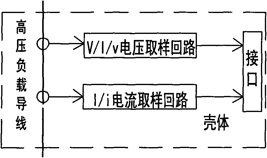
[0029] like figure 1 Shown:

[0030] The V / I / v voltage sampling circuit and the I / i current sampling circuit are set in the measured high-voltage load wire in the housing, and the output terminals of the V / I / v voltage sampling circuit and the output terminals of the I / i current sampling circuit are respectively connected to the On the current interface and voltage interface of the output interface of the shell.

[0031] The output end of the V / I / v voltage sampling loop and the output end of the I / i current sampling loop are respectively connected to the current interface and the voltage interface of the interface provided at the outlet of the casing.

[0032] The V / I / v voltage sampling circuit obtains the voltage signal from the high-voltage load wire and the current signal obtained by the I / i current sampling circuit from the high-voltage load wire. The output signal is a weak signal mV, mA level, which can be an analog signal or The digital signals are respectively connect...

Embodiment 2

[0043] like Figure 4 Shown:

[0044] The three-phase three-wire V-v connection of the I / i current sampling circuit: the primary side of the micro-current output sensors T7 and T8 is a single-turn winding of the high-voltage load wire A-phase and C-phase, and the secondary side is connected to the interface U1.

[0045] Connect the three-phase high-voltage load wires to two phases for sampling. The principle of the method is the same as the three-phase four-wire Y-y connection.

[0046] like Figure 5 Shown:

[0047] The three-phase three-wire V-v connection method of the V / I / v voltage sampling circuit, sampling any two phases of the three-phase AC high voltage. The primary sides of the current detectors T9 and T10 of phase A and phase C are set to a common terminal and connected to phase B, and the output terminals of the secondary side are respectively connected in parallel with resistors R9 and R10, and one end of the resistors R9 and R10 is respectively connected to th...


PUM


Abstract

The invention relates to a combined type sensor, which belongs to the field of electric power measurements. The combined type sensor comprises a shell, and is characterized in that a V / I / v voltage sampling loop and an I / i current sampling loop are arranged on a measured high-voltage load conducting wire in the shell, and an output end of the V / I / v voltage sampling loop and an output end of the I / icurrent sampling loop are connected with a current interface and a voltage interface of an output interface of the shell respectively. The combined type sensor can acquire supplied weak current signals, supplies the signals to a measuring instrument of milliampere or microampere standard current signals and millivolts or microvolt standard voltage signals to perform measurement, can acquire the signals accurately, reduce the consumption, save the cost and prevent electric larceny, is save and stable, and is suitable for measuring the electric quantity of a high-voltage side.

Description

technical field [0001] The invention relates to a combined sensor and belongs to the field of electric power measurement. Specifically, it is a combined sensor suitable for a power metering device on the high-voltage side. Background technique [0002] High-voltage electric energy metering device is a metering instrument used in the process of power generation, supply and consumption. It involves the economic interests of the three parties of power generation, supply and consumption. Its fairness and justice are very important. It has a wide range of applications and is an indispensable electric energy. metering device. At present, a high-voltage electric energy metering device is generally composed of multiple high-voltage current transformers and multiple high-voltage voltage transformers, an electric energy meter, a terminal box, a high-voltage terminal connection bar, and a low-voltage connection wire. The high-voltage voltage transformer transforms the high-voltage vo...

Claims


Application Information

Patent Timeline
Patent Type & Authority Applications(China)
IPC IPC(8): G01R15/00G01R11/00G01R22/06
Inventor 荣博苗军张庆华张丽
Owner 淄博计保互感器研究所(有限公司)
Learn More