Pull-out mechanism for a drawer

A drawer and track technology, applied in the field of pull-out mechanism, can solve the problems of complex and easily damaged pull-out mechanism, and achieve the effects of simple, reliable transmission and reliable sliding of the pull-out mechanism

Inactive Publication Date: 2010-02-03
INTER IKEA SYST
View PDF2 Cites 8 Cited by
  • Summary
  • Abstract
  • Description
  • Claims
  • Application Information

AI Technical Summary

Problems solved by technology

Pairs of rollers and bearing balls are placed between the tracks; however, the bearing balls complicate the pull-out mechanism and are therefore vulnerable

Method used


Image

  • Pull-out mechanism for a drawer
  • Pull-out mechanism for a drawer
  • Pull-out mechanism for a drawer

Examples


Embodiment Construction

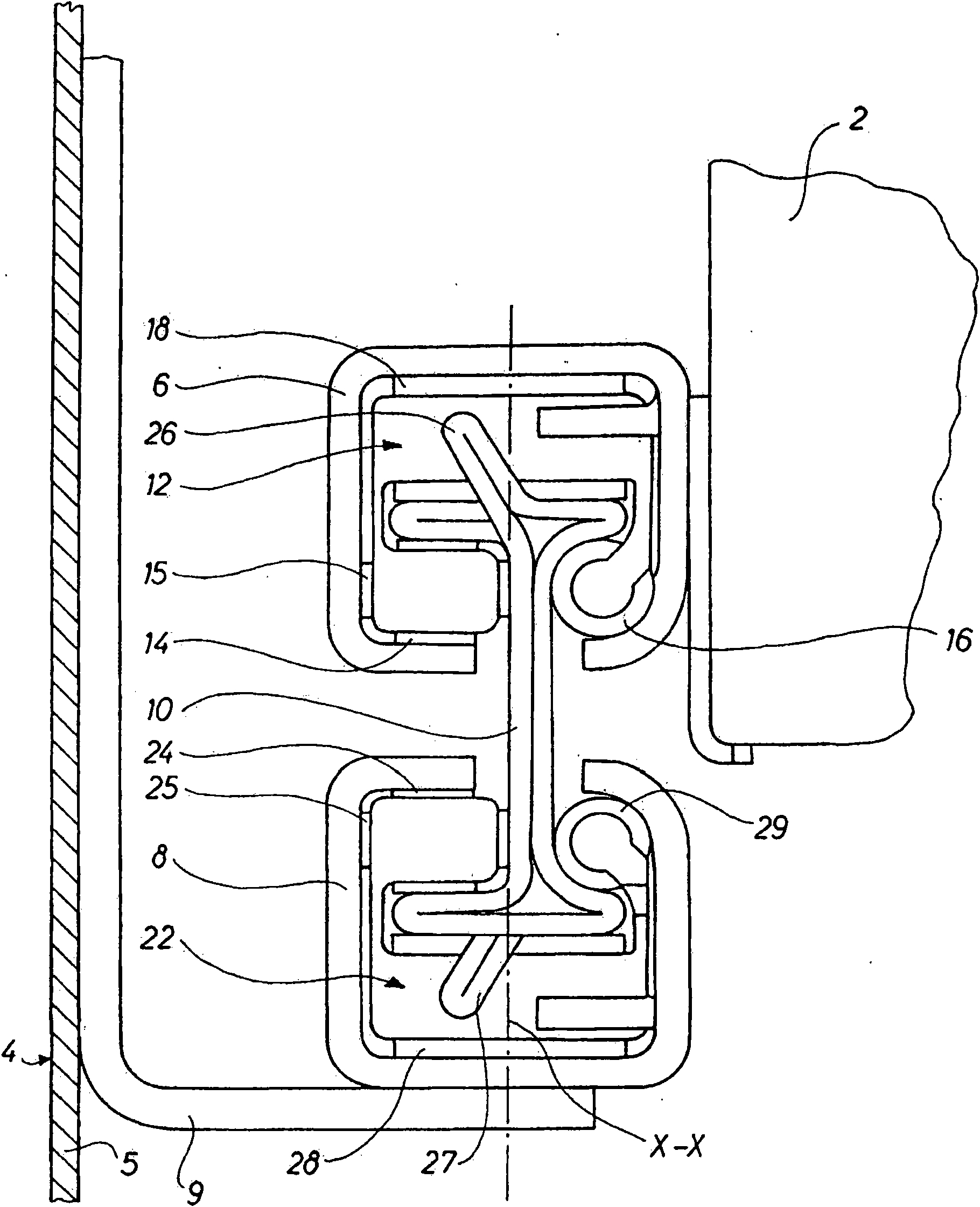
[0018] figure 1 and 4 The pull-out mechanism 1 shown in is used to install a preferably large and heavy drawer 2 in a drawer cavity 3 in a piece of furniture 4 . This piece of furniture 4 can be, for example, a filing cabinet. The pull-out mechanism 1 comprises an upper pull-out rail 6 and a lower rail 8, the upper pull-out rail 6 is in the longitudinal direction of the drawer (ie perpendicular to figure 1 The direction of the middle file plane) is fastened to the drawer 2, while the lower rail 8 is fastened to the wall 5 in the drawer cavity 3 of the piece of furniture 4 by means of fittings 9. An intermediate rail 10 is interposed between the upper rail 6 and the lower rail 8, said intermediate rail 10 being movable in its longitudinal direction, see Figure 4 , while the middle track 10 is placed between tracks 6 and 8 . Between the middle rail 10 and the upper rail 6 - while at the same time to the left of this middle rail 10, especially its vertical center plane X-X -...


PUM


Abstract

A pull-out mechanism for a drawer (2) in a drawer cavity (3) in a piece of furniture (4). The pull-out mechanism includes an upper rail (8) with a substantially U-shaped cross- section, said rail being affixed to the drawer (2) in its longitudinal direction, and possibly a lower rail (8) with a substantially U-shaped cross section, said lower rail, possibly indirectly, being affixed to a wall (5)in the drawer cavity (3), and an intermediate rail (10) which in its longitudinal direction is movable between the upper rail and the lower rail. At least one bearing holder (12, 22) with roller (14,15, 24, 25) and balls (16, 29) is inserted between the intermediate rail and the upper rail and the lower rail respectively. Exactly one bearing ball (16, 29) is mounted in the part of the individualbearing holder (12, 22) placed on one side of the intermediate rail (10); two rollers or wheels (14, 15, 24, 25) are mounted in the part of the individual bearing holder (12, 22) placed on the other side of the intermediate rail (10). The axes of rotation of said rollers or wheels are placed in each their plane of two planes standing perpendicular to each other. A substantially horizontal auxiliary roller (18, 28) extending to both sides of the intermediate rail (10) is mounted in the individual bearing holder (12, 22) between the intermediate rail (10) and the upper rail (6) and the lower rail (8) respectively. Hereby a considerably constructive simplification is achieved and the pull-out mechanism can bear both horizontal and vertical loads in a reliable way. Furthermore it is possible to pull out the drawer to a position just outside the actual piece of furniture.

Description

technical field [0001] The invention relates to a pull-out mechanism for mounting preferably large and heavy drawers in a drawer cavity of a piece of furniture, in particular a filing cabinet, and said pull-out mechanism comprises: an upper rail, said upper pull-out rail being fixed to the drawer in its longitudinal direction; and a possibly lower rail having a substantially U-shaped cross-section, said lower rail being possibly indirectly fixed to a wall in the drawer cavity upper; and an intermediate rail, which is movable along its longitudinal direction between the upper rail and the lower rail, and where at least one bearing cage with rollers and balls is respectively inserted between the intermediate rail and the upper rail and between the middle track and the lower track. Background technique [0002] A mechanism for drawers is known where a central rail is placed between an upper rail connected to a telescoping drawer and a lower rail connected to a closet of which ...

Claims


Application Information

Patent Timeline
Patent Type & Authority Applications(China)
IPC IPC(8): A47B88/10A47B88/493
CPCA47B2210/0037A47B2210/0059A47B88/10A47B2210/0043A47B2210/001A47B2210/0056A47B2210/0032A47B88/493
Inventor T·约翰森
Owner INTER IKEA SYST
Why Eureka
Try Eureka