Draining pump

A technology of drainage pump and pump cover, applied in the direction of pumps, pump components, non-variable-capacity pumps, etc., can solve the problems of unsatisfactory water retaining effect of water retaining ring, low drainage pressure, and inability of drainage pump to drain water, etc. Practical and promotional value, the effect of increasing the drainage pressure and improving the water retaining effect

Inactive Publication Date: 2010-02-03
NAN TONG HUAGUAN ELECTRIC CO LTD
View PDF0 Cites 2 Cited by
  • Summary
  • Abstract
  • Description
  • Claims
  • Application Information

AI Technical Summary

Problems solved by technology

In the existing market, there are many drainage pumps with drainage functions similar to those of the drainage pump of the present invention, but there are also many problems such as: only a few layers of insulating tape paper are used for the surface insulation treatment of the enameled wire on the surface of the coil, which is far from being able to adapt to the high temperature and high temperature of the drainage pump. Requirements for long-term use in a wet environment; the coil is not equipped with any over-temperature protection measures or a one-time thermal fuse is used, which will cause the motor to break when abnormal conditions occur, and the drainage pump will be scrapped; the impeller of the drainage pump and the motor shaft are combined with compression fit and adhesive Long-term use will easily cause the impeller to slip, causing the drainage pump to fail to drain water. At the same time, the water retention effect of the water retaining ring is not ideal, which makes the drainage pump prone to failure; and the fixed bracket of the existing drainage pump is separated from the left and right brackets. The fixed structure of the drainage pump causes the displacement of the fixed position of the drainage pump, which is time-consuming to install, and it is easy to cause the installation of the water pump to be unstable; the impeller of the current drainage pump adopts a structure in which the blades are perpendicular to the tangent of the impeller, so that the drainage pressure is not high and there is noise during use. High, so it is necessary to improve the existing drainage pump to meet the actual needs

Method used


Image

  • Draining pump
  • Draining pump
  • Draining pump

Examples


Embodiment Construction

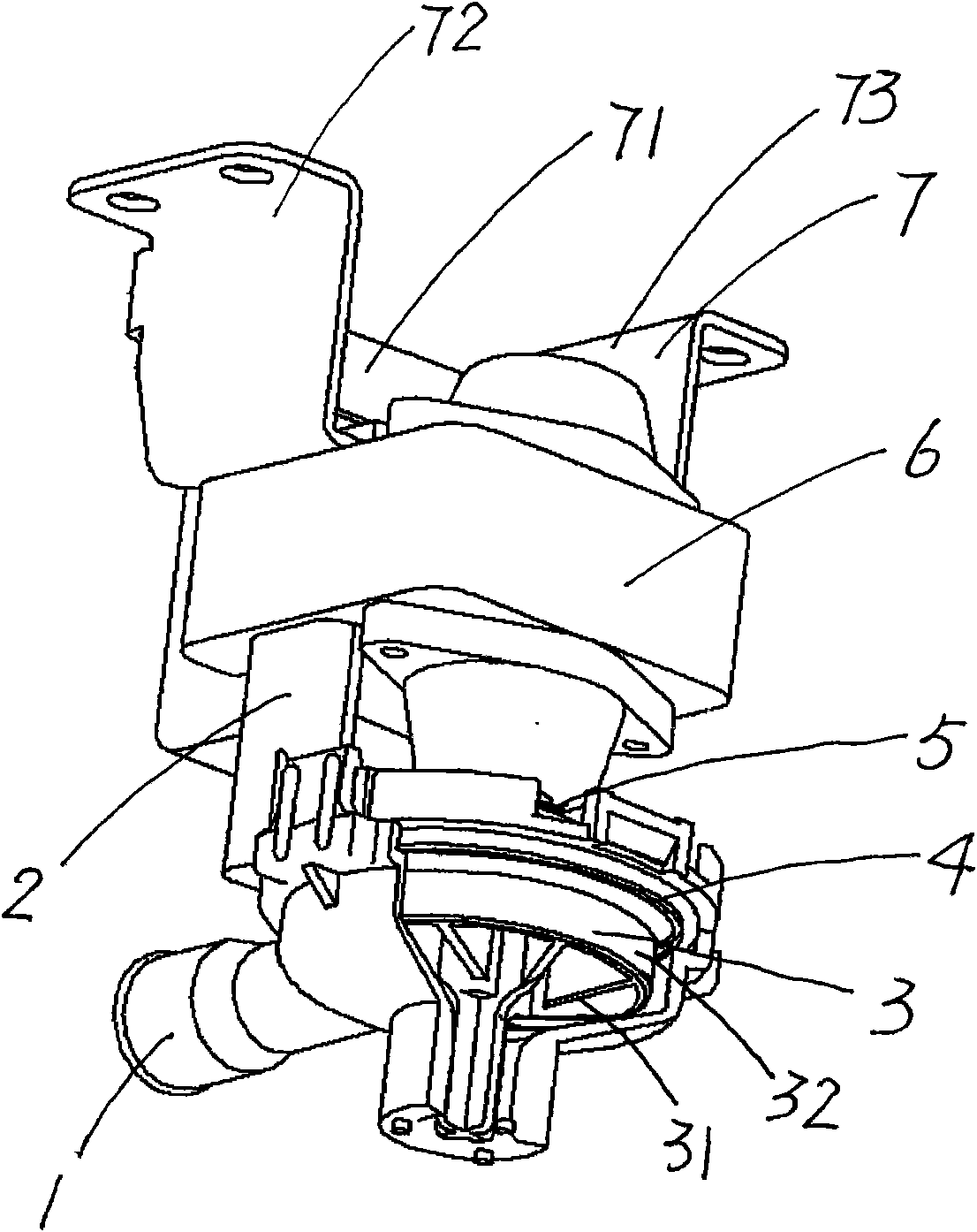
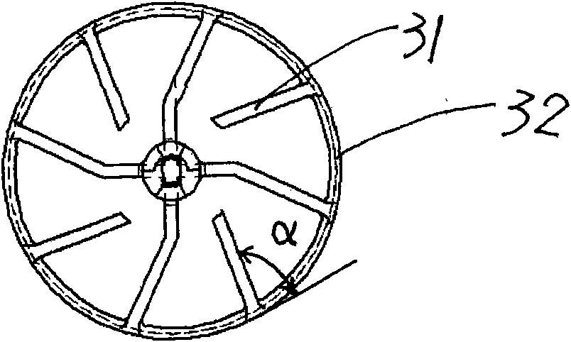
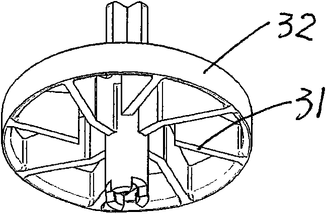
[0018] Refer to attached figure 1 , attached figure 2 , attached image 3 , a drainage pump of the present invention, which is composed of a pump cover 1, a bracket 2, an impeller 3, a sealing ring 4, a water retaining ring 5, a shaded pole motor 6, and a fixed bracket 7, and a bracket is fixed on the shaded pole motor 6 2. The impeller 3 connected with the shaded pole motor 6 is arranged in the inner cavity of the pump cover 1 under the bracket 2; the water retaining ring 5 is arranged on the shaft of the shaded pole motor 6; the sealing ring 4 is arranged on the bracket 2 and At the junction of the pump cover 1, a fixed bracket 7 with a side reinforced connecting plate 71 is also provided on the shaded pole motor 6, and the reinforced connecting plate 71 of the fixed bracket 7 is in phase with the bracket seat I 72 and the bracket seat II 73. connect. The blade 31 in the impeller 3 and the tangent to the impeller side 32 form an inclination angle α, and the inclination a...


PUM


Abstract

The invention relates to a draining pump, which is used in air conditioners and washing machines for draining water. The draining pump comprises a pump cover, a bracket, an impeller, a water retainingring, a shaded pole motor, a fixed bracket and the like, wherein the shaded pole motor is fixedly provided with the bracket; the impeller connected with the shaded pole motor is arranged in an innercavity of the pump cover under the bracket; the shaft of the shaded pole motor is provided with the water retaining ring; the shaded pole motor is also provided with the fixed bracket having laterallyreinforcing and connecting plates; the blades in the impeller form an inclined angle alpha with a tangent of the edge of the impeller; as the inclined angle is formed between the blades in the impeller and the tangent of the edge of the impeller, the pressure for draining water is improved and the noises are reduced; as the water retaining ring is provided with ribs and a protruding edge, the water retaining effect is improved; as the fixed bracket is designed to have a structure with the laterally reinforcing and connecting plates, the installation is convenient; and as the inside of the shaded pole motor is provided with a restorable temperature protector and the end closure of the motor is provided with a protruding structure, the motor can be protected from abnormal temperature.

Description

technical field [0001] The invention relates to a drainage pump, in particular to a drainage pump used for draining air conditioners and washing machines. Background technique [0002] After retrieving relevant patent documents, no drainage pump with the same structure as the present invention has been found. In the existing market, there are many drainage pumps with drainage functions similar to those of the drainage pump of the present invention, but there are also many problems such as: only a few layers of insulating tape paper are used for the surface insulation treatment of the enameled wire on the surface of the coil, which is far from being able to adapt to the high temperature and high temperature of the drainage pump. Requirements for long-term use in a wet environment; the coil is not equipped with any over-temperature protection measures or a one-time thermal fuse is used, which will cause the motor to break when abnormal conditions occur, and the drainage pump w...

Claims


Application Information

Patent Timeline
Patent Type & Authority Applications(China)
IPC IPC(8): F04D29/24F04D29/60F04D29/08F04D29/00
Inventor 张从泉沈长明
Owner NAN TONG HUAGUAN ELECTRIC CO LTD
Why Eureka
Try Eureka