
Injection valve

A technology of injection valve and valve body, which is applied in the direction of fuel injection device, fuel injection valve driven by fluid pressure, charging system, etc., can solve problems such as large leakage, achieve large wall thickness, improve compressive strength, optimal The effect of using

Inactive Publication Date: 2010-02-03
CONTINENTAL AUTOMOTIVE GMBH
View PDF2 Cites 0 Cited by
  • Summary
  • Abstract
  • Description
  • Claims
  • Application Information

AI Technical Summary

Problems solved by technology

[0004] Relatively large leakage due to fuel pressure in the case of injection valves supplied with high-pressure fuel

Method used


Image

  • Injection valve
  • Injection valve
  • Injection valve

Examples


Embodiment Construction

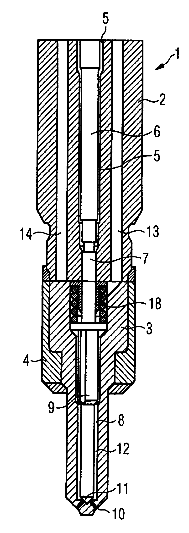
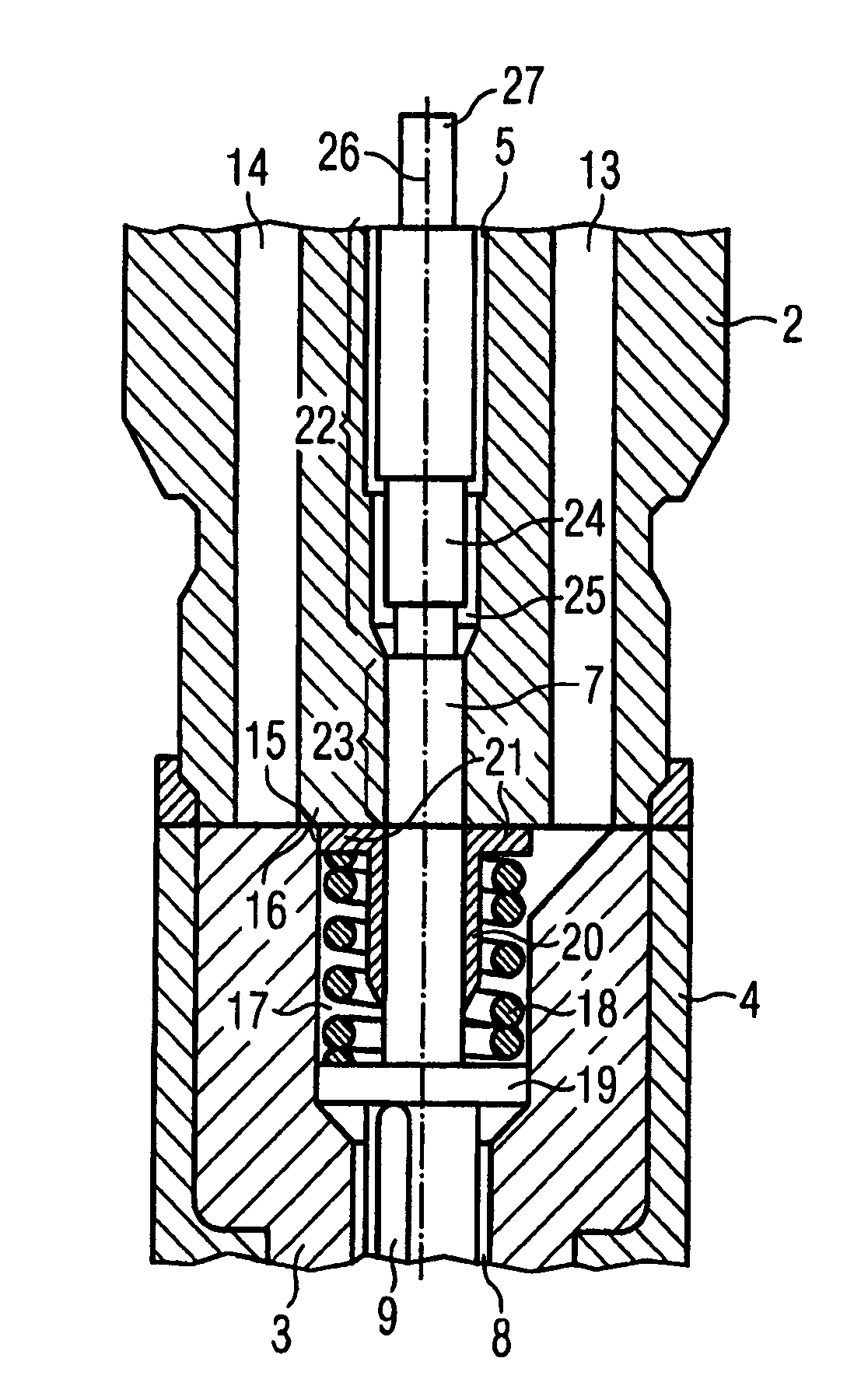
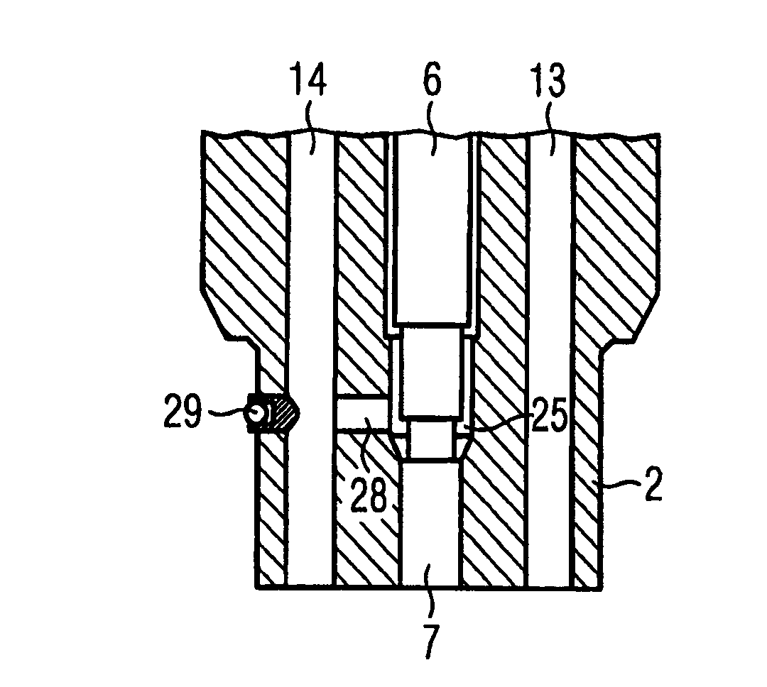
[0022] figure 1 It is a schematic illustration of the lower part of the injection valve 1 with the valve body 2 and the nozzle body 3 . The valve body 2 is located directly on the nozzle body 3 and is clamped with the valve body 2 by the nozzle clamping nut 4 . Opened in valve body 2 is a first bore 5 which is arranged along the longitudinal axis of injector 1 . A control piston 6 and a stroke adjustment screw 7 are arranged in the first bore 5 .

[0023] Opened in the nozzle body 3 is a second bore 8 in which a nozzle needle 9 is arranged axially displaceable. An injection opening 10 is provided at the lower end of the nozzle body 3 , wherein a sealing seat 11 is provided upstream in the flow direction on the inner side of the nozzle body 3 , which can be closed off by the nozzle needle 9 . A nozzle chamber 12 is provided between the nozzle needle 9 and the nozzle body 3 , which communicates with a fuel line 13 . Furthermore, a leakage line 14 is provided in the valve bod...


PUM


Abstract

The present invention relates to an injection valve having a valve body and a nozzle body which is resting in a sealing fashion against the valve body, with a first valve body bore, in which bore a control piston and a stroke adjusting bolt are arranged so as to be moveable in the axial direction, with the control piston being embodied in order to be moved by a control means, with a second bore being provided in the nozzle body, with a nozzle needle being arranged in the second bore, the nozzle needle being provided to open or close an injection opening, with a tension spring being provided in the second bore, the tension spring stressing the nozzle needle in the direction of a sealing seat for the injection opening, with the first and second bore being actively connected to one another and with the stroke adjusting bolt being actively connected to the nozzle needle.

Description

technical field [0001] The invention relates to an injection valve according to claim 1 . Background technique [0002] To supply the internal combustion engine with fuel, injectors are used which are supplied with fuel via fuel lines or a common rail system. [0003] For controlling the injection valve, a piezoelectric actuator is used as the actuating device, which actuator controls the nozzle needle directly or indirectly via a servo valve. [0004] In the case of injection valves which are supplied with high-pressure fuel, relatively large leakages occur due to the fuel pressure. In addition, the high pressure of the injection valve requires a thicker wall of the injection valve. Contents of the invention [0005] The object of the invention is to propose an injection valve with an improved design. [0006] The object of the invention is achieved by an injection valve according to claim 1 . [0007] In the case of the injection valve according to the invention, the...

Claims


Application Information

Patent Timeline
Patent Type & Authority Applications(China)
IPC IPC(8): F02M61/10F02M51/06
CPCF02M47/027F02M55/002F02M61/20F02M2547/006
Inventor M·汉尼奇
Owner CONTINENTAL AUTOMOTIVE GMBH
Learn More