Industrial engineering head for computer cutting and proofing

An industrial and engineering technology, which is applied in the field of tool heads, can solve the problem that the drawing pen assembly, the pressure wheel assembly and the vibrating knife assembly cannot be disassembled and interchanged, and achieve the effect of humanized loading and unloading operation, convenient disassembly and interchange, and simple and easy disassembly

Active Publication Date: 2010-01-27
SHANGHAI XINAO TECH
View PDF1 Cites 6 Cited by
  • Summary
  • Abstract
  • Description
  • Claims
  • Application Information

AI Technical Summary

Problems solved by technology

[0002] The applicant applied for an invention patent on May 19, 2008. The name is "a multi-functional tool head integrating drawing, cutting and cutting press wheels". The application number is "200820058593.7". This invention realizes cutting, folding and marking In one automatic operation, but the stroke pen assembly, pressure wheel assembly and vibrating knife assembly of the invention cannot be disassembled and interchanged

Method used


Image

  • Industrial engineering head for computer cutting and proofing
  • Industrial engineering head for computer cutting and proofing
  • Industrial engineering head for computer cutting and proofing

Examples


Embodiment

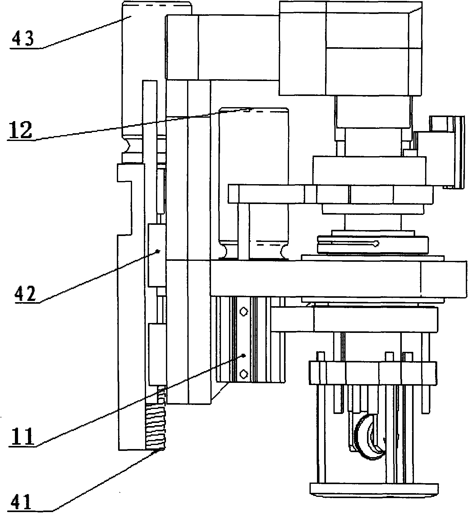
[0017] Such as Figure 1A and Figure 1B As shown, it is a structural schematic diagram of an industrial engineering head for computer cutting and proofing. The industrial engineering head for computer cutting and proofing includes a main mounting plate 1, a synchronous wheel assembly 2, a support plate 3, a press Foot assembly 4, rear mounting plate 5, rotating sleeve assembly 6, tool head locking assembly 7, pen assembly 8, pressure wheel assembly 9, vibrating knife assembly 10, air cylinder assembly 11 and servo motor assembly 12.

[0018] The main mounting plate 1 is vertically installed on the rear mounting plate 5 through the support plates 3 on both sides, and the detachable drawing pen assembly 8, pressing pen assembly 8, and pressing pen are vertically installed on the main mounting plate 1 by rotating the sleeve assembly 6 and the tool head locking assembly 7. The wheel assembly 9 and the vibrating knife assembly 10, the drawing pen assembly 8, the pressure wheel ass...


PUM


Abstract

The invention relates to an industrial engineering head for computer cutting and proofing. The head is characterized by comprising a main mounting plate, the main mounting plate is vertically arranged on a rear mounting plate by supporting plates on both sides thereof, a removable metal marker assembly, a pinch roller assembly and a vibrating knife assembly are vertically arranged on the main mounting plate by a rotary shaft sleeve assembly and an end lock assembly, the metal marker assembly, the pinch roller assembly and the vibrating knife assembly are parallel to each other, lower ends of the metal marker assembly, the pinch roller assembly and the vibrating knife assembly are equipped with a presser foot assembly respectively, rear sides of the metal marker assembly, the pinch roller assembly and the vibrating knife assembly are equipped with a cylinder assembly, the cylinder assembly is connected with a servo motor assembly, and the servo motor assembly is connected with the rotary shaft sleeves of the metal marker assembly, the pinch roller assembly and the vibrating knife assembly respectively. The industrial engineering head has the advantage of being removable and replaceable.

Description

technical field [0001] The invention relates to an industrial engineering machine head for computer cutting and proofing, which can be used for carton and carton packaging proofing, and belongs to the technical field of tool heads. Background technique [0002] The applicant applied for an invention patent on May 19, 2008. The name is "a multi-functional tool head integrating drawing, cutting and cutting press wheels". The application number is "200820058593.7". This invention realizes cutting, folding and marking In one automatic operation, but the pen assembly, pressure wheel assembly and vibrating knife assembly of the invention cannot be disassembled and interchanged. Contents of the invention [0003] The purpose of the present invention is to provide a detachable and interchangeable industrial engineering head for computer cutting and proofing. Compared with previous heads, the head has the characteristics of small size, compact structure, high precision, and conveni...

Claims


Application Information

Patent Timeline
Patent Type & Authority Applications(China)
IPC IPC(8): B31B1/20B25H7/04B31B50/20
Inventor 胡永凯
Owner SHANGHAI XINAO TECH
Why Eureka
Try Eureka