
Fiber cable cross connection box

A fiber optic cable transfer box and fiber optic cable technology, applied in the physical field, can solve the problems of optical splitters without ideal installation facilities, and achieve the effect of reducing the difficulty and cost of installation

Inactive Publication Date: 2009-12-30
SHANGHAI POSTS & TELECOMM DESIGNING CONSULTING INST
View PDF0 Cites 3 Cited by
  • Summary
  • Abstract
  • Description
  • Claims
  • Application Information

AI Technical Summary

Problems solved by technology

[0003] The object of the present invention is to provide an optical cable transfer box, which solves the technical problem that optical splitters do not have ideal installation facilities in the prior art

Method used


Image

  • Fiber cable cross connection box

Examples


Embodiment 1

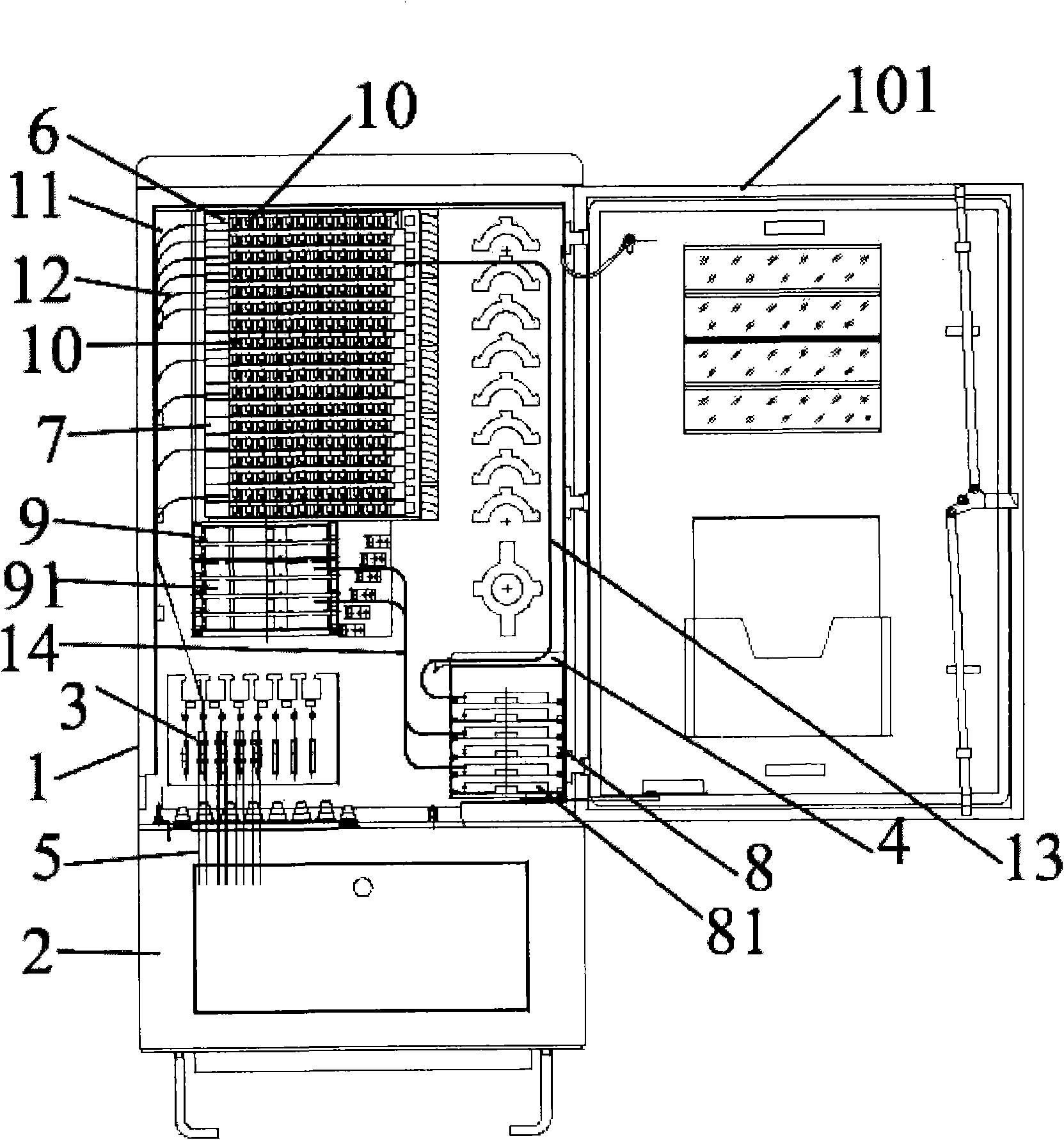
[0013] Such as figure 1 As shown, the present invention provides an optical cable transfer box, which is composed of a box body 1 and a base 2, and the box body 1 is provided with a box door 101, and the box body 1 is provided with an uplink optical cable welding unit 6, a downlink An optical cable fusion unit 7, an optical cable fastening unit 3 and a fiber storage unit 4, the optical cable 5 enters the box 1 through the optical cable fastening unit 3 and is connected to the optical cable fusion unit, wherein the box 1 An optical splitter installation unit 8 and an optical splitter pigtail fiber storage unit 9 are also provided in the optical splitter installation unit 8. At least one optical splitter 81 is arranged on the optical splitter installation unit 8. The optical splitter The pigtail fiber storage unit 9 is provided with at least one optical splitter pigtail fiber storage box 91, the uplink optical cable 11 enters the box body 1 through the optical cable fastening un...


PUM


Abstract

The invention relates to a fiber cable cross connection box, which consists of a box body and a pedestal, wherein the box body is provided with an uplink fiber cable welding unit, a downlink fiber cable welding unit, a fiber cable fastening unit and a fiber-holding storage unit; the box body is also provided with an optical splitter mounting unit and an optical splitter tail fiber storage unit; the optical splitter mounting unit is provided with an optical splitter; and the optical splitter tail fiber storage unit is provided with an optical splitter tail fiber storage box, and output end standby tail fibers are spirally stored in the optical splitter tail fiber storage box. The box body is provided with the optical splitter and the optical splitter tail fiber storage unit, so that the fiber cable cross connection box has the optical branching function, can flexibly performs jumper connection between an uplink fiber cable and a downlink fiber cable, can flexibly configure the number of optical branches, prevent that a room is occupied independently to arrange the optical splitter and a fiber cable forming end, reduces the arrangement difficulty and the cost of the optical splitter, and has flexible use.

Description

Technical field: [0001] The invention relates to the field of physics, in particular to communication technology, in particular to an optical cable junction box. Background technique: [0002] In order to improve the bandwidth of users accessing network service providers and greatly eliminate the line signal loss of copper cable access network, passive optical network (PON) access technology has been adopted in the existing technology to replace high-speed optical fiber media network with low line loss. Copper cable media network with line loss. Passive optical network (PON) technology uses optical splitter as the core device of its optical distribution network (ODN). In order to facilitate integration with existing optical networks, save optical fiber resources of optical cables or be limited by pipeline resources, and for safety reasons, optical splitters, as sub-nodes of optical access networks, need to be installed in optical cable transfer boxes, but optical cable tran...

Claims


Application Information

Patent Timeline
Patent Type & Authority Applications(China)
IPC IPC(8): G02B6/44
Inventor 严森垒
Owner SHANGHAI POSTS & TELECOMM DESIGNING CONSULTING INST
Learn More