Temperature indicator segmentation compensating device

A compensating device and indicator technology, applied to thermometers, thermometer parts, measuring devices, etc., can solve the problems of increasing measurement errors and unable to completely eliminate ambient temperature errors, reduce temperature measurement errors, and facilitate popularization and application , easy-to-make effects

Active Publication Date: 2013-10-02
杭州科宏仪器仪表有限公司
View PDF8 Cites 0 Cited by
  • Summary
  • Abstract
  • Description
  • Claims
  • Application Information

AI Technical Summary

Problems solved by technology

In fact, different measured temperatures require different amounts of compensation. Some temperature indicators do not even require ambient temperature compensation when measuring low temperatures. Therefore, a single temperature compensation system cannot completely eliminate errors caused by ambient temperature. Some even Increased measurement error in the local measurement range

Method used


Image

  • Temperature indicator segmentation compensating device
  • Temperature indicator segmentation compensating device
  • Temperature indicator segmentation compensating device

Examples


Embodiment 2

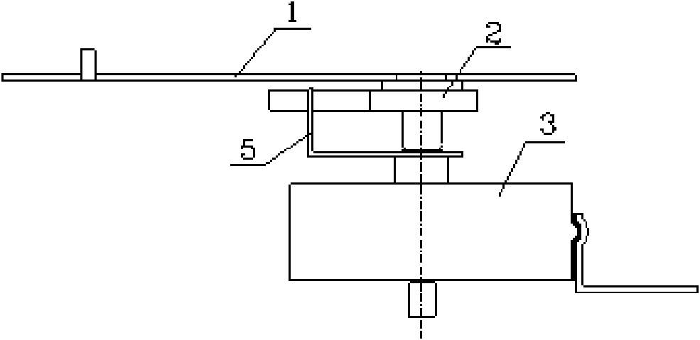
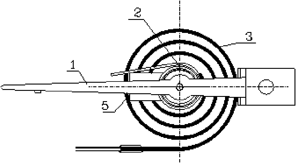
[0037]Embodiment 2 of the present invention: as the second embodiment of the present invention, as Figure 9-Figure 12 As shown, it also includes a temperature pointer 1, a compensation system, and a Bourdon tube 3. The compensation system is fixedly connected to the rotating shaft of the temperature pointer 1. A compensation sheet II4 is coaxially connected under the compensation sheet I2, and a compensation sheet II4 is installed under the compensation sheet II4. Push rod 5, Bowden tube 3 is housed below the push rod 5. Wherein, push rod 5 is "∟" shape, and its transverse section is fixed on the rotating shaft. The track groove disc 6 that the rod 5 rotates. A track groove is provided on the track groove disk 6, and the track groove includes a connected inner track 7 and an outer track 8, and the vertical section of the push rod 5 extends downwards and snaps into the track groove.

[0038] Also according to the setting (realized by setting the deviation between the outer t...

Embodiment 3

[0040] Embodiment 3 of the present invention: as the third embodiment of the present invention, as Figure 13-Figure 16 As shown, compared with embodiment 2, the track groove plate 6 is replaced by the cam plate 10 and the tension spring 11 below it, and the lower end of the vertical section of the push rod 5 is stuck on the outer edge of the cam plate 10, and is held by the tension spring 11 pull, under the pull of tension spring 11, make the motion locus of push rod 5 follow the shape of cam disc 10 (see the shape of cam disc 10 Figure 17 As shown) changes, the vertical section of the push rod 5 is pushed by the short handle of the compensation piece II or the long handle of the compensation piece I2 in different temperature ranges, so as to realize the segmental temperature compensation.

[0041] Other unspecified items are the same as in Embodiment 2.


PUM

PropertyMeasurementUnit
lengthaaaaaaaaaa

Abstract

The invention discloses a temperature indicator segmentation compensating device which comprises a temperature pointer (1), a compensation system and a Bourdon tube (3), wherein the compensation system consists a compensation strip i (2) and a compensation strip ii (4); the revolving shaft of the compensation system is fixedly connected with that of the temperature pointer (1); the compensation strip ii (4) is coaxially connected below the compensation strip i (2); a push rod (5) is arranged below the compensation strip ii (4); and the Bourdon tube (3) is arranged below the push rod (5). The compensation strip ii is arranged coaxially to the compensation strip I, and an eccentricity is arranged between the revolving shaft of the push rood and that of the compensation system and the temperature pointer, or a track groove plate or a cam plate is arranged to limit the rotating track of the push rod so as to realize segmentation compensation of temperature. The temperature indicator is effectively compensated by the segmentation compensating device, thus further reducing the temperature detection error; in addition, the compensating device has simple structure, easy manufacture and low cost, and is beneficial to popularization and application.

Description

technical field [0001] The invention relates to a temperature compensating device for a temperature indicator, in particular to a temperature compensating device capable of section compensation. Background technique [0002] Transformers, especially large power transformers, will generate a lot of heat during work, causing the internal temperature of the transformer to rise. When the temperature is too high, it is easy to cause accidents. Therefore, a temperature measuring device is often equipped to monitor the internal temperature of the transformer. . The temperature measuring devices currently used are all inserted into the top of the transformer oil tank through a probe. The internal pressure of the liquid or gas in the probe changes due to temperature changes, and is transmitted to the multi-turn Bowden tube through the capillary tube, causing the axis of the multi-turn Bowden tube to rotate. The temperature is indicated by the pointer on the dial. Since the capillar...

Claims


Application Information

Patent Timeline
Patent Type & Authority Patents(China)
IPC IPC(8): G01K1/24
Inventor 余海震孙兵
Owner 杭州科宏仪器仪表有限公司
Why Eureka
Try Eureka